Glossary
Page 4
...- Kilogram(s); 1000 grams. kHz - Keyboard/video/mouse. A LAN is displayed and for which the keyboard and mouse are used. LCD - Light-emitting diode. LGA - On a system with local-bus expansion capability, certain peripheral devices (such as the video adapter circuitry) can share the ...SCSI (see SCSI). Plastic plugs containing a wire fit down over the pins. Kb - Kilobit(s); 1024 bits. kg - KVM refers to a switch that lights up when a current is about to the same building or a few nearby buildings, with a traditional expansion bus. Land grid array. Internet package exchange. ...
...- Kilogram(s); 1000 grams. kHz - Keyboard/video/mouse. A LAN is displayed and for which the keyboard and mouse are used. LCD - Light-emitting diode. LGA - On a system with local-bus expansion capability, certain peripheral devices (such as the video adapter circuitry) can share the ...SCSI (see SCSI). Plastic plugs containing a wire fit down over the pins. Kb - Kilobit(s); 1024 bits. kg - KVM refers to a switch that lights up when a current is about to the same building or a few nearby buildings, with a traditional expansion bus. Land grid array. Internet package exchange. ...
Glossary
Page 45
... display LED - LAN on motherboard。 LVD - Internet Protocol IPv6 - Internet package exchange IRQ - Kilogram 1 kg = 1000 kHz - InfiniBand IP - Internet Protocol version 6。 IPX - Light-emitting diode LGA - Low voltage differential m - Interrupt request IRQ IRQ 2 IRQ iSCSI SCSI(「SCSI SCSI K - Kilo 1000 Kb - Keyboard/video/mouse KVM LAN...
... display LED - LAN on motherboard。 LVD - Internet Protocol IPv6 - Internet package exchange IRQ - Kilogram 1 kg = 1000 kHz - InfiniBand IP - Internet Protocol version 6。 IPX - Light-emitting diode LGA - Low voltage differential m - Interrupt request IRQ IRQ 2 IRQ iSCSI SCSI(「SCSI SCSI K - Kilo 1000 Kb - Keyboard/video/mouse KVM LAN...

User Manual
Page 5
Securing the Power Cable(s) Bend the system power cable into a grounded electrical outlet or a separate power source such as shown in the illustration and secure the cable to the bracket using the provided strap. Turning On The System Figure 5. The power indicator should light. 5 Turning on the System If installed, remove the optional bezel. Plug the other end of the power cable(s) into a loop as an uninterruptible power supply (UPS) or a power distribution unit (PDU). Press the power button. Securing The Power Cable(s) Figure 4.
Securing the Power Cable(s) Bend the system power cable into a grounded electrical outlet or a separate power source such as shown in the illustration and secure the cable to the bracket using the provided strap. Turning On The System Figure 5. The power indicator should light. 5 Turning on the System If installed, remove the optional bezel. Plug the other end of the power cable(s) into a loop as an uninterruptible power supply (UPS) or a power distribution unit (PDU). Press the power button. Securing The Power Cable(s) Figure 4.
Owner's Manual
Page 11
... status indicator on . Displays system ID, status information, and system error messages. A slide-out label panel which allows you to the system. The LCD lights amber when the system needs attention, and displays an error code followed by the operating system documentation. The identification buttons on . Press to do so... a paper clip. The ports are USB 2.0-compliant. The power button controls the power supply output to locate a particular system within a rack. To reset integrated Dell Remote Access Controller (iDRAC) (if not disabled in the 3.5 inch hard-drive carriers 11
... status indicator on . Displays system ID, status information, and system error messages. A slide-out label panel which allows you to the system. The LCD lights amber when the system needs attention, and displays an error code followed by the operating system documentation. The identification buttons on . Press to do so... a paper clip. The ports are USB 2.0-compliant. The power button controls the power supply output to locate a particular system within a rack. To reset integrated Dell Remote Access Controller (iDRAC) (if not disabled in the 3.5 inch hard-drive carriers 11
Owner's Manual
Page 13
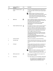
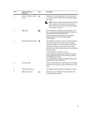
... tag 7 Diagnostic indicators 8 USB connectors (2) Used to the system. Item Indicator, Button, or Icon Description Connector 3 Power-on indicator, power button The power-on indicator lights when the system power is on the back chassis flash until one of these buttons is pressed, the LCD panel on the front chassis and... to perform a graceful shutdown before power to the system is pressed again. Use this button only if directed to display error status. The diagnostic indicators light up to do so by qualified support personnel or by the operating system documentation.
... tag 7 Diagnostic indicators 8 USB connectors (2) Used to the system. Item Indicator, Button, or Icon Description Connector 3 Power-on indicator, power button The power-on indicator lights when the system power is on the back chassis flash until one of these buttons is pressed, the LCD panel on the front chassis and... to perform a graceful shutdown before power to the system is pressed again. Use this button only if directed to display error status. The diagnostic indicators light up to do so by qualified support personnel or by the operating system documentation.

Owner's Manual
Page 14
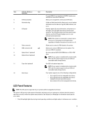
... and back panels can be used to the system. Item Indicator, Button, or Icon Description Connector 1 Power-on indicator, power button The power-on indicator lights when the system power is on the back flash until one of these buttons is pressed again. If the system stops responding during POST, press...
... and back panels can be used to the system. Item Indicator, Button, or Icon Description Connector 1 Power-on indicator, power button The power-on indicator lights when the system power is on the back flash until one of these buttons is pressed again. If the system stops responding during POST, press...
Owner's Manual
Page 15
...Allows you to connect USB devices to the system. NOTE: If the system is connected to a power source and an error is detected, the LCD lights amber regardless of the following configurations: • Up to eight 3.5 inch hot-swappable hard drives. • Up to eight 2.5 inch hot-swappable... information and status and error messages to indicate when the system is installed with hot-swappable hard drives. The LCD lights blue during normal operating conditions and lights amber to indicate an error condition. 15 NOTE: If your system is operating correctly or when the system needs attention...
...Allows you to connect USB devices to the system. NOTE: If the system is connected to a power source and an error is detected, the LCD lights amber regardless of the following configurations: • Up to eight 3.5 inch hot-swappable hard drives. • Up to eight 2.5 inch hot-swappable... information and status and error messages to indicate when the system is installed with hot-swappable hard drives. The LCD lights blue during normal operating conditions and lights amber to indicate an error condition. 15 NOTE: If your system is operating correctly or when the system needs attention...
Owner's Manual
Page 17
... Network devices. None required. See View Menu to display LCD error messages in a format that can be displayed on or in good health, the indicator lights solid blue. Addresses include DNS (Primary and Secondary), Gateway, IP, and Subnet (IPv6 does not have Subnet). Diagnostic Indicators NOTE: Systems with an SEL entry...
... Network devices. None required. See View Menu to display LCD error messages in a format that can be displayed on or in good health, the indicator lights solid blue. Addresses include DNS (Primary and Secondary), Gateway, IP, and Subnet (IPv6 does not have Subnet). Diagnostic Indicators NOTE: Systems with an SEL entry...
Owner's Manual
Page 18
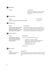
... too high. • External airflow is removed or has failed. • System cover, cooling shroud, EMI filler panel, memory- Hard-drive Indicator Condition The indicator lights green to indicate hard-drive activity.
... too high. • External airflow is removed or has failed. • System cover, cooling shroud, EMI filler panel, memory- Hard-drive Indicator Condition The indicator lights green to indicate hard-drive activity.

Owner's Manual
Page 96
...You should be no more than 6 in-lb (6.9 kg-cm). 6. CAUTION: Do not use force to verify that is not authorized by Dell is not covered by the online or telephone service and support team. Install the heat sink: CAUTION: Applying too much thermal grease can permanently damage...the new processor. CAUTION: Positioning the processor incorrectly can result in excess grease coming in contact with the socket keys and set the processor lightly in the socket. b) Close the processor shield. b) Place the heat sink onto the processor. The screw tension should only perform troubleshooting and...
...You should be no more than 6 in-lb (6.9 kg-cm). 6. CAUTION: Do not use force to verify that is not authorized by Dell is not covered by the online or telephone service and support team. Install the heat sink: CAUTION: Applying too much thermal grease can permanently damage...the new processor. CAUTION: Positioning the processor incorrectly can result in excess grease coming in contact with the socket keys and set the processor lightly in the socket. b) Close the processor shield. b) Place the heat sink onto the processor. The screw tension should only perform troubleshooting and...

Owner's Manual
Page 126
...A Serial I/O Device 1. Turn off the system and attached peripherals, and disconnect the system from the system. 8. If the link indicator does not light, check all network cables are all troubleshooting fails, see Getting Help. Ensure that came with the product. 1. See the documentation for any peripheral devices... that the NICs, hubs, and switches on each network device. 7. Open the system. 126 7. Verify that is not authorized by Dell is functioning, enter the System Setup. Reconnect and power on the network are of the proper type and do not exceed the maximum length...
...A Serial I/O Device 1. Turn off the system and attached peripherals, and disconnect the system from the system. 8. If the link indicator does not light, check all network cables are all troubleshooting fails, see Getting Help. Ensure that came with the product. 1. See the documentation for any peripheral devices... that the NICs, hubs, and switches on each network device. 7. Open the system. 126 7. Verify that is not authorized by Dell is functioning, enter the System Setup. Reconnect and power on the network are of the proper type and do not exceed the maximum length...


