Getting Started Guide
Page 10
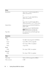
... Serial USB Video Front USB Internal USB Video Video type Video memory Up to four 3.5-inch hot-plug SAS or SATA internal drives or Up to four 3.5-inch cabled SAS or SATA internal drives or Up to four 2.5-inch hot-plug SAS or SSD internal drives in iDRAC 8 MB 8 Getting Started With..., 16550-compatible Four 4-pin, USB 2.0-compliant 15-pin VGA Two 4-pin, USB 2.0-compliant Two 4-pin, USB 2.0-compliant Matrox G200, integrated in a 3.5-inch carrier. Optional internal SATA DVD-ROM or DVD+/-RW Optional external USB DVD-ROM NOTE: DVD devices are data only.
... Serial USB Video Front USB Internal USB Video Video type Video memory Up to four 3.5-inch hot-plug SAS or SATA internal drives or Up to four 3.5-inch cabled SAS or SATA internal drives or Up to four 2.5-inch hot-plug SAS or SSD internal drives in iDRAC 8 MB 8 Getting Started With..., 16550-compatible Four 4-pin, USB 2.0-compliant 15-pin VGA Two 4-pin, USB 2.0-compliant Two 4-pin, USB 2.0-compliant Matrox G200, integrated in a 3.5-inch carrier. Optional internal SATA DVD-ROM or DVD+/-RW Optional external USB DVD-ROM NOTE: DVD devices are data only.
Hardware Owner's Manual
Page 4
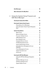
... Messages 58 Using the System Setup Program Navigation Keys 58 System Setup Options 59 Main Screen 59 Memory Settings Screen 61 Processor Settings Screen 62 SATA Settings Screen 62 Boot Settings Screen 63 Integrated Devices Screen 64 PCI IRQ Assignment Screen 65 Serial Communication Screen 65 Embedded Server Management Screen (Optional...
... Messages 58 Using the System Setup Program Navigation Keys 58 System Setup Options 59 Main Screen 59 Memory Settings Screen 61 Processor Settings Screen 62 SATA Settings Screen 62 Boot Settings Screen 63 Integrated Devices Screen 64 PCI IRQ Assignment Screen 65 Serial Communication Screen 65 Embedded Server Management Screen (Optional...

Hardware Owner's Manual
Page 12
Front-Panel Features and Indicators NOTE: Depending on the configuration, your system may have either an LCD panel or LED diagnostic indicators. Figure 1-1. Front Panel Features and Indicators 10 9 1 8 7 6 5 4 2 3 Item Indicator, Button, or Icon Description Connector 1 Front bezel lock Secures the front bezel to the system. 2 Tape drive/Optical drive (optional) One optional internal half-height tape backup device or an optical drive 3 Optical drive (optional) Optional internal SATA DVD-ROM or DVD+/-RW NOTE: DVD devices are data only. 12 About Your System
Front-Panel Features and Indicators NOTE: Depending on the configuration, your system may have either an LCD panel or LED diagnostic indicators. Figure 1-1. Front Panel Features and Indicators 10 9 1 8 7 6 5 4 2 3 Item Indicator, Button, or Icon Description Connector 1 Front bezel lock Secures the front bezel to the system. 2 Tape drive/Optical drive (optional) One optional internal half-height tape backup device or an optical drive 3 Optical drive (optional) Optional internal SATA DVD-ROM or DVD+/-RW NOTE: DVD devices are data only. 12 About Your System

Hardware Owner's Manual
Page 47
...configuration. Read fault Requested sector not found to the Replace the faulty drive. SATA port x device auto-sensing error The drive connected to the specified SATA port. SATA port x device configuration error SATA port x device error About Your System 47 See "General Memory Module Installation ... USB Device" on page 148, "Troubleshooting an Optical Drive" on page 158, or "Troubleshooting a Hard Drive" on page 108. SATA Portx There is faulty. single rank or dual rank DIMM in your system. device not found The operating system cannot Replace the optical ...
...configuration. Read fault Requested sector not found to the Replace the faulty drive. SATA port x device auto-sensing error The drive connected to the specified SATA port. SATA port x device configuration error SATA port x device error About Your System 47 See "General Memory Module Installation ... USB Device" on page 148, "Troubleshooting an Optical Drive" on page 158, or "Troubleshooting a Hard Drive" on page 108. SATA Portx There is faulty. single rank or dual rank DIMM in your system. device not found The operating system cannot Replace the optical ...
Hardware Owner's Manual
Page 54
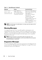
..." on selected drive Causes Faulty USB device, USB medium, optical drive assembly, hard drive, or hard-drive subsystem. Ensure that the USB, SAS backplane, or SATA cables are generated by typing y (yes) or n (no). For example, before the system continues a task. NOTE: Warning messages are properly connected. For more information about...
..." on selected drive Causes Faulty USB device, USB medium, optical drive assembly, hard drive, or hard-drive subsystem. Ensure that the USB, SAS backplane, or SATA cables are generated by typing y (yes) or n (no). For example, before the system continues a task. NOTE: Warning messages are properly connected. For more information about...
Hardware Owner's Manual
Page 60
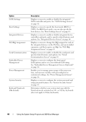
... integrated device controllers and ports, and to 84-key keyboards). 60 Using the System Setup Program and UEFI Boot Manager Option SATA Settings Boot Settings Integrated Devices PCI IRQ Assignment Serial Communication Embedded Server Management Power Management System Security Keyboard NumLock (On default) ...screen to change the IRQ assigned to specify the boot mode (BIOS or UEFI). See "Serial Communication Screen" on page 66. See "SATA Settings Screen" on page 67. Displays a screen to enable or disable the serial ports and specify related features and options. See "System...
... integrated device controllers and ports, and to 84-key keyboards). 60 Using the System Setup Program and UEFI Boot Manager Option SATA Settings Boot Settings Integrated Devices PCI IRQ Assignment Serial Communication Embedded Server Management Power Management System Security Keyboard NumLock (On default) ...screen to change the IRQ assigned to specify the boot mode (BIOS or UEFI). See "Serial Communication Screen" on page 66. See "SATA Settings Screen" on page 67. Displays a screen to enable or disable the serial ports and specify related features and options. See "System...
Hardware Owner's Manual
Page 62
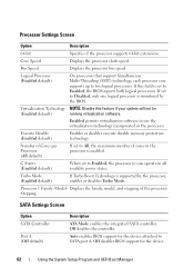
... in the processor. If set to All, the maximum number of the processor Stepping SATA Settings Screen Option SATA Controller Port A (Off default) Description ATA Mode enables the integrated SATA controller. Execute Disable (Enabled default) Enables or disables execute disable memory protection technology.... Off disables BIOS support for the device attached to Disabled, only one logical processor is set to SATA port A. If this feature if your system will not be (Enabled default) running virtualization software. Turbo Mode (Enabled default)...
... in the processor. If set to All, the maximum number of the processor Stepping SATA Settings Screen Option SATA Controller Port A (Off default) Description ATA Mode enables the integrated SATA controller. Execute Disable (Enabled default) Enables or disables execute disable memory protection technology.... Off disables BIOS support for the device attached to Disabled, only one logical processor is set to SATA port A. If this feature if your system will not be (Enabled default) running virtualization software. Turbo Mode (Enabled default)...
Hardware Owner's Manual
Page 63
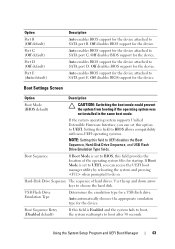
...BIOS support for the device. Setting this field to BIOS allows compatibility with non-UEFI operating systems. NOTE: Setting this option to SATA port C. Auto automatically chooses the appropriate emulation type for the device. Use the up and down arrow keys to UEFI disables the...default) Port C (Off default) Port D (Off default) Port E (Auto default) Description Auto enables BIOS support for the device attached to SATA port E. Off disables BIOS support for the device. Auto enables BIOS support for the device attached to UEFI. Hard-Disk Drive Sequence The sequence of...
...BIOS support for the device. Setting this field to BIOS allows compatibility with non-UEFI operating systems. NOTE: Setting this option to SATA port C. Auto automatically chooses the appropriate emulation type for the device. Use the up and down arrow keys to UEFI disables the...default) Port C (Off default) Port D (Off default) Port E (Auto default) Description Auto enables BIOS support for the device attached to SATA port E. Off disables BIOS support for the device. Auto enables BIOS support for the device attached to UEFI. Hard-Disk Drive Sequence The sequence of...
Hardware Owner's Manual
Page 90
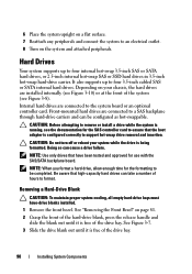
... Hard-Drive Blank CAUTION: To maintain proper system cooling, all empty hard-drive bays must have been tested and approved for use with the SAS/SATA backplane board. See "Removing the Front Bezel" on the system and attached peripherals. Front-mounted hard drives are connected to a SAS backplane through hard... that have -drive blanks installed. 1 Remove the front bezel. Hard Drives Your system supports up to four internal hot-swap 3.5-inch SAS or SATA hard drives, or 2.5-inch internal hot-swap SAS or SSD hard drives in 3.5-inch hot-swap hard-drive carrier. It also supports up to ...
... Hard-Drive Blank CAUTION: To maintain proper system cooling, all empty hard-drive bays must have been tested and approved for use with the SAS/SATA backplane board. See "Removing the Front Bezel" on the system and attached peripherals. Front-mounted hard drives are connected to a SAS backplane through hard... that have -drive blanks installed. 1 Remove the front bezel. Hard Drives Your system supports up to four internal hot-swap 3.5-inch SAS or SATA hard drives, or 2.5-inch internal hot-swap SAS or SSD hard drives in 3.5-inch hot-swap hard-drive carrier. It also supports up to ...
Hardware Owner's Manual
Page 93
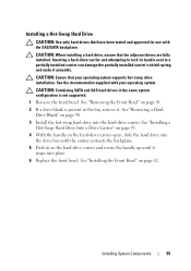
...Replace the front bezel. CAUTION: Ensure that your operating system. Installing System Components 93 See "Removing a HardDrive Blank" on page 82. CAUTION: Combining SATA and SAS hard drives in the same system configuration is present in on page 81. 2 If a drive blank is not supported. 1 Remove the... that have been tested and approved for use with your operating system supports hot-swap drive installation. See the documentation supplied with the SAS/SATA backplane. See "Installing a Hot-Swap Hard Drive Into a Drive Carrier" on page 95. 4 With the handle on the hard-drive...
...Replace the front bezel. CAUTION: Ensure that your operating system. Installing System Components 93 See "Removing a HardDrive Blank" on page 82. CAUTION: Combining SATA and SAS hard drives in the same system configuration is present in on page 81. 2 If a drive blank is not supported. 1 Remove the... that have been tested and approved for use with your operating system supports hot-swap drive installation. See the documentation supplied with the SAS/SATA backplane. See "Installing a Hot-Swap Hard Drive Into a Drive Carrier" on page 95. 4 With the handle on the hard-drive...

Hardware Owner's Manual
Page 94
Figure 3-9. Removing and Installing a Hot-Swap Hard Drive 1 2 1 hard drive 3 SAS/SATA screw hole 4 3 2 screws (4) 4 hard-drive carrier 94 Installing System Components Removing a Hot-Swap Hard Drive From a Hard-Drive Carrier Remove the screws from the slide rails on the hard-drive carrier and separate the hard drive from the carrier. See Figure 3-9.
Figure 3-9. Removing and Installing a Hot-Swap Hard Drive 1 2 1 hard drive 3 SAS/SATA screw hole 4 3 2 screws (4) 4 hard-drive carrier 94 Installing System Components Removing a Hot-Swap Hard Drive From a Hard-Drive Carrier Remove the screws from the slide rails on the hard-drive carrier and separate the hard drive from the carrier. See Figure 3-9.
Hardware Owner's Manual
Page 97
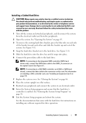
...by a certified service technician. Damage due to an electrical outlet. 10 Enter the System Setup program and ensure that is not authorized by Dell is enabled. See "Closing the System" on page 86. 8 Place the system upright on installing any peripherals and connect the system ...drive for instructions on a flat surface. 9 Reattach any software required for drive operation. NOTE: If connecting to the integrated SATA controller (SATA hard drives only), connect the SATA data cable to the hard drive. See Figure 6-1. See the documentation that came with the product. 1 Turn off the ...
...by a certified service technician. Damage due to an electrical outlet. 10 Enter the System Setup program and ensure that is not authorized by Dell is enabled. See "Closing the System" on page 86. 8 Place the system upright on installing any peripherals and connect the system ...drive for instructions on a flat surface. 9 Reattach any software required for drive operation. NOTE: If connecting to the integrated SATA controller (SATA hard drives only), connect the SATA data cable to the hard drive. See Figure 6-1. See the documentation that came with the product. 1 Turn off the ...
Hardware Owner's Manual
Page 158
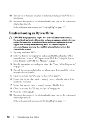
... instructions that came with the product. 1 Try using a different DVD. 2 Enter the System Setup program and ensure that is not authorized by Dell is not resolved, see "Getting Help" on page 165. 4 Turn off the system and attached peripherals, and disconnect the system from the electrical... the system and attached peripherals. See "Using Online Diagnostics" on page 177. Damage due to servicing that the integrated SATA controller and the drive's SATA port are enabled. If the problem is not covered by your product documentation, or as directed by a certified service technician....
... instructions that came with the product. 1 Try using a different DVD. 2 Enter the System Setup program and ensure that is not authorized by Dell is not resolved, see "Getting Help" on page 165. 4 Turn off the system and attached peripherals, and disconnect the system from the electrical... the system and attached peripherals. See "Using Online Diagnostics" on page 177. Damage due to servicing that the integrated SATA controller and the drive's SATA port are enabled. If the problem is not covered by your product documentation, or as directed by a certified service technician....
Hardware Owner's Manual
Page 159
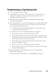
.... b Open the system. d Ensure that the tape drive's interface cable is fully connected to the connector on the controller card (SAS or SCSI) or the SATA connector on the controller card. See "Using Online Diagnostics" on page 85. See "Opening the System" on page 165. f Close the system. Troubleshooting Your System...
.... b Open the system. d Ensure that the tape drive's interface cable is fully connected to the connector on the controller card (SAS or SCSI) or the SATA connector on the controller card. See "Using Online Diagnostics" on page 85. See "Opening the System" on page 165. f Close the system. Troubleshooting Your System...
Hardware Owner's Manual
Page 185
... a modem to the system BIOS and then display an error message on the system used . See also guarding, mirroring, and RAID. Super video graphics array. SATA - sec - serial port - Allows hard drives to report errors and failures to the system. The amount of the space on each disk. Data stored in... System Setup program is installed and how the system should be configured for technical support. A legacy I /O bus interface with a 9-pin connector that allows you call Dell for operation. Second(s). SVGA - SDRAM -
... a modem to the system BIOS and then display an error message on the system used . See also guarding, mirroring, and RAID. Super video graphics array. SATA - sec - serial port - Allows hard drives to report errors and failures to the system. The amount of the space on each disk. Data stored in... System Setup program is installed and how the system should be configured for technical support. A legacy I /O bus interface with a 9-pin connector that allows you call Dell for operation. Second(s). SVGA - SDRAM -


