Hardware Owner's Manual
Page 3
Contents 1 About Your System 11 Accessing System Features During Startup 11 Front-Panel Features and Indicators 12 LCD Panel Features (Optional 14 Home Screen 15 Setup Menu 16 View Menu 17 Hard-Drive Indicator Patterns 18 Back-Panel Features and Indicators 19 Guidelines for Connecting External Devices 21 NIC Indicator Codes 21 Power Indicator Codes 22 Diagnostic Lights (Optional 23 LCD Status Messages 25 Viewing Status Messages 26 Removing LCD Status Messages 26 System Messages 39 Warning Messages 54 Diagnostics Messages 54 Contents 3
Contents 1 About Your System 11 Accessing System Features During Startup 11 Front-Panel Features and Indicators 12 LCD Panel Features (Optional 14 Home Screen 15 Setup Menu 16 View Menu 17 Hard-Drive Indicator Patterns 18 Back-Panel Features and Indicators 19 Guidelines for Connecting External Devices 21 NIC Indicator Codes 21 Power Indicator Codes 22 Diagnostic Lights (Optional 23 LCD Status Messages 25 Viewing Status Messages 26 Removing LCD Status Messages 26 System Messages 39 Warning Messages 54 Diagnostics Messages 54 Contents 3
Hardware Owner's Manual
Page 9
... RAID Controller . . . . 161 Troubleshooting Expansion Cards 162 Troubleshooting the Processor 163 5 Running the System Diagnostics 165 Using Online Diagnostics 165 Embedded System Diagnostics Features 165 When to Use the Embedded System Diagnostics . . . . 166 Running the Embedded System Diagnostics 166 System Diagnostics Testing Options 167 Using the Custom Test Options 167 Selecting Devices for Testing 167 Contents 9
... RAID Controller . . . . 161 Troubleshooting Expansion Cards 162 Troubleshooting the Processor 163 5 Running the System Diagnostics 165 Using Online Diagnostics 165 Embedded System Diagnostics Features 165 When to Use the Embedded System Diagnostics . . . . 166 Running the Embedded System Diagnostics 166 System Diagnostics Testing Options 167 Using the Custom Test Options 167 Selecting Devices for Testing 167 Contents 9
Hardware Owner's Manual
Page 10
Selecting Diagnostics Options 167 Viewing Information and Results 168 6 Jumpers and Connectors 169 System Board Jumpers 169 System Board Connectors 170 SAS Backplane Board Connectors 173 Power Distribution Board Connectors 174 Disabling a Forgotten Password 174 7 Getting Help 177 Contacting Dell 177 Glossary 179 Index 189 10 Contents
Selecting Diagnostics Options 167 Viewing Information and Results 168 6 Jumpers and Connectors 169 System Board Jumpers 169 System Board Connectors 170 SAS Backplane Board Connectors 173 Power Distribution Board Connectors 174 Disabling a Forgotten Password 174 7 Getting Help 177 Contacting Dell 177 Glossary 179 Index 189 10 Contents
Hardware Owner's Manual
Page 11
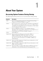
About Your System Accessing System Features During Startup The following keystrokes provide access to access utilities such as embedded system diagnostics. Enters System Services, which allows access to the System Event Log (SEL) and configuration of remote access to configure NIC settings for your integrated NIC. ...
About Your System Accessing System Features During Startup The following keystrokes provide access to access utilities such as embedded system diagnostics. Enters System Services, which allows access to the System Event Log (SEL) and configuration of remote access to configure NIC settings for your integrated NIC. ...

Hardware Owner's Manual
Page 12
Front Panel Features and Indicators 10 9 1 8 7 6 5 4 2 3 Item Indicator, Button, or Icon Description Connector 1 Front bezel lock Secures the front bezel to the system. 2 Tape drive/Optical drive (optional) One optional internal half-height tape backup device or an optical drive 3 Optical drive (optional) Optional internal SATA DVD-ROM or DVD+/-RW NOTE: DVD devices are data only. 12 About Your System Figure 1-1. Front-Panel Features and Indicators NOTE: Depending on the configuration, your system may have either an LCD panel or LED diagnostic indicators.
Front Panel Features and Indicators 10 9 1 8 7 6 5 4 2 3 Item Indicator, Button, or Icon Description Connector 1 Front bezel lock Secures the front bezel to the system. 2 Tape drive/Optical drive (optional) One optional internal half-height tape backup device or an optical drive 3 Optical drive (optional) Optional internal SATA DVD-ROM or DVD+/-RW NOTE: DVD devices are data only. 12 About Your System Figure 1-1. Front-Panel Features and Indicators NOTE: Depending on the configuration, your system may have either an LCD panel or LED diagnostic indicators.
Hardware Owner's Manual
Page 13
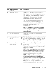
... seconds. Item Indicator, Button, or Icon Connector 4 LED or LCD panel 5 LCD menu buttons Description LED panel - The power-on . See "Diagnostic Lights (Optional)" on the front panel can take several seconds up to over 2 minutes to navigate the control panel LCD menu. 6 System identification button...causes the system to perform a graceful shutdown before power to the system is connected to the system. LCD panel - The four diagnostic indicator lights display error codes during normal system operation. The LCD lights amber when the system needs attention, and the LCD panel displays...
... seconds. Item Indicator, Button, or Icon Connector 4 LED or LCD panel 5 LCD menu buttons Description LED panel - The power-on . See "Diagnostic Lights (Optional)" on the front panel can take several seconds up to over 2 minutes to navigate the control panel LCD menu. 6 System identification button...causes the system to perform a graceful shutdown before power to the system is connected to the system. LCD panel - The four diagnostic indicator lights display error codes during normal system operation. The LCD lights amber when the system needs attention, and the LCD panel displays...
Hardware Owner's Manual
Page 23
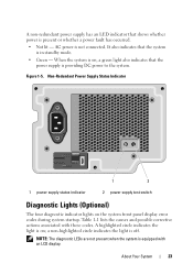
... lit - a non-highlighted circle indicates the light is on the system front panel display error codes during system startup. About Your System 23 NOTE: The diagnostic LEDs are not present when the system is not connected. AC power is equipped with these codes. A non-redundant power supply has an LED indicator... that shows whether power is providing DC power to the system. Non-Redundant Power Supply Status Indicator 1 2 1 power supply status indicator 2 power supply test switch Diagnostic Lights (Optional) The four diagnostic indicator lights on ;
... lit - a non-highlighted circle indicates the light is on the system front panel display error codes during system startup. About Your System 23 NOTE: The diagnostic LEDs are not present when the system is not connected. AC power is equipped with these codes. A non-redundant power supply has an LED indicator... that shows whether power is providing DC power to the system. Non-Redundant Power Supply Status Indicator 1 2 1 power supply status indicator 2 power supply test switch Diagnostic Lights (Optional) The four diagnostic indicator lights on ;
Hardware Owner's Manual
Page 24
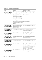
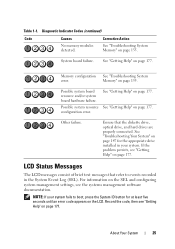
Diagnostic Indicator Codes Code Causes Corrective Action The system is in recovery mode. operating condition after the system successfully boots to the operating system. BIOS checksum ... press the pre-BIOS failure has power button. Possible video failure. Ensure that the diskette drive and hard drive are not lit after POST. The diagnostic lights are properly connected. Possible processor failure. Possible expansion card See "Troubleshooting Expansion failure. Cards" on page 177. See "Getting Help" on page 162. Table...
Diagnostic Indicator Codes Code Causes Corrective Action The system is in recovery mode. operating condition after the system successfully boots to the operating system. BIOS checksum ... press the pre-BIOS failure has power button. Possible video failure. Ensure that the diskette drive and hard drive are not lit after POST. The diagnostic lights are properly connected. Possible processor failure. Possible expansion card See "Troubleshooting Expansion failure. Cards" on page 177. See "Getting Help" on page 162. Table...
Hardware Owner's Manual
Page 25
Diagnostic Indicator Codes (continued) Code Causes No memory modules detected. System board failure. Possible system board resource and/or system board hardware failure. See "Getting Help" ...
Diagnostic Indicator Codes (continued) Code Causes No memory modules detected. System board failure. Possible system board resource and/or system board hardware failure. See "Getting Help" ...
Hardware Owner's Manual
Page 54
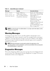
... optical drive assembly, hard drive, or hard-drive subsystem. For more information about system diagnostics. 54 About Your System NOTE: Warning messages are properly connected. See "Running the System Diagnostics" on page 165 for more information, see the "Glossary" on page 179. Warning messages... usually interrupt the task and require you run diagnostic tests on the diskette. Ensure that accompanied the operating system or application. For example, before the system continues a task. ...
... optical drive assembly, hard drive, or hard-drive subsystem. For more information about system diagnostics. 54 About Your System NOTE: Warning messages are properly connected. See "Running the System Diagnostics" on page 165 for more information, see the "Glossary" on page 179. Warning messages... usually interrupt the task and require you run diagnostic tests on the diskette. Ensure that accompanied the operating system or application. For example, before the system continues a task. ...

Hardware Owner's Manual
Page 68
... unchanged (all user settings for the TPM are cleared. Back up the TPM keys prior to enabling this button halts the operating system and displays a diagnostic screen. On an ACPI-compliant operating system, the system performs an orderly shutdown before power is disabled. The No Change state initiates no action. This...
... unchanged (all user settings for the TPM are cleared. Back up the TPM keys prior to enabling this button halts the operating system and displays a diagnostic screen. On an ACPI-compliant operating system, the system performs an orderly shutdown before power is disabled. The No Change state initiates no action. This...

Hardware Owner's Manual
Page 70
... you wish to the UEFI Boot Manager screen from the other program screens. Moves to access the System Setup program, System Services Unified Server Configurator, Diagnostics, and BIOS-level boot options. 70 Using the System Setup Program and UEFI Boot Manager Displays the list of boot options. Enables you to and...
... you wish to the UEFI Boot Manager screen from the other program screens. Moves to access the System Setup program, System Services Unified Server Configurator, Diagnostics, and BIOS-level boot options. 70 Using the System Setup Program and UEFI Boot Manager Displays the list of boot options. Enables you to and...
Hardware Owner's Manual
Page 71
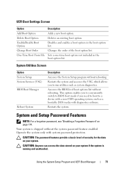
.... This option enables you to conveniently switch to BIOS boot mode if you to a device with a non-UEFI operating system, such as system diagnostics. System and Setup Password Features NOTE: For a forgotten password, see "Disabling a Forgotten Password" on your system if the system is shipped without...in the boot option list. Restarts the system. Using the System Setup Program and UEFI Boot Manager 71 Operate the system only with diagnostics software. Change Boot Order Changes the order of security for the data on page 174. Restarts the system and accesses the USC, ...
.... This option enables you to conveniently switch to BIOS boot mode if you to a device with a non-UEFI operating system, such as system diagnostics. System and Setup Password Features NOTE: For a forgotten password, see "Disabling a Forgotten Password" on your system if the system is shipped without...in the boot option list. Restarts the system. Using the System Setup Program and UEFI Boot Manager 71 Operate the system only with diagnostics software. Change Boot Order Changes the order of security for the data on page 174. Restarts the system and accesses the USC, ...

Hardware Owner's Manual
Page 75
... during the boot sequence and can use the Password Status option in conjunction with Baseboard Management Controller (BMC): • Installing an operating system • Running diagnostics to protect the system password from an embedded environment throughout the server's lifecycle. The following features of the operating system. NOTE: You can function independently...
... during the boot sequence and can use the Password Status option in conjunction with Baseboard Management Controller (BMC): • Installing an operating system • Running diagnostics to protect the system password from an embedded environment throughout the server's lifecycle. The following features of the operating system. NOTE: You can function independently...
Hardware Owner's Manual
Page 79
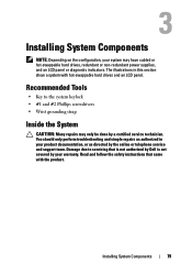
... may have cabled or hot-swappable hard drives, redundant or non-redundant power supplies, and an LCD panel or diagnostic indicators. Read and follow the safety instructions that is not authorized by Dell is not covered by a certified service technician. You should only perform troubleshooting and simple repairs as authorized in this...
... may have cabled or hot-swappable hard drives, redundant or non-redundant power supplies, and an LCD panel or diagnostic indicators. Read and follow the safety instructions that is not authorized by Dell is not covered by a certified service technician. You should only perform troubleshooting and simple repairs as authorized in this...
Hardware Owner's Manual
Page 103
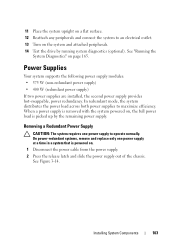
See "Running the System Diagnostics" on . 1 Disconnect the power cable from the power supply. 2 Press the release latch and slide the power supply out of the chassis. Power Supplies Your .... 12 Reattach any peripherals and connect the system to an electrical outlet. 13 Turn on , the full power load is picked up by running system diagnostics (optional). Removing a Redundant Power Supply CAUTION: The system requires one power supply at a time in a system that is powered on page 165. In redundant mode...
See "Running the System Diagnostics" on . 1 Disconnect the power cable from the power supply. 2 Press the release latch and slide the power supply out of the chassis. Power Supplies Your .... 12 Reattach any peripherals and connect the system to an electrical outlet. 13 Turn on , the full power load is picked up by running system diagnostics (optional). Removing a Redundant Power Supply CAUTION: The system requires one power supply at a time in a system that is powered on page 165. In redundant mode...
Hardware Owner's Manual
Page 113
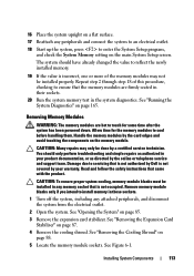
... or telephone service and support team. Remove memory-module blanks only if you intend to ensure that came with the product. See "Running the System Diagnostics" on page 88. 5 Locate the memory module sockets. See "Removing the Expansion Card Stabilizer" on page 85. 3 Remove the expansion card stabilizer... an electrical outlet. 18 Start up the system, press to servicing that is not covered by your product documentation, or as directed by Dell is not occupied. Removing Memory Modules WARNING: The memory modules are firmly seated in their sockets. 20 Run the system memory test in...
... or telephone service and support team. Remove memory-module blanks only if you intend to ensure that came with the product. See "Running the System Diagnostics" on page 88. 5 Locate the memory module sockets. See "Removing the Expansion Card Stabilizer" on page 85. 3 Remove the expansion card stabilizer... an electrical outlet. 18 Start up the system, press to servicing that is not covered by your product documentation, or as directed by Dell is not occupied. Removing Memory Modules WARNING: The memory modules are firmly seated in their sockets. 20 Run the system memory test in...
Hardware Owner's Manual
Page 130
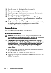
... any peripherals and connect the system to an electrical outlet. 16 Turn on page 58. 18 Run the system diagnostics to enter the System Setup program, and check that is not authorized by Dell is not covered by a certified service technician. System Battery The system battery is incorrectly installed. 13 Close the...
... any peripherals and connect the system to an electrical outlet. 16 Turn on page 58. 18 Run the system diagnostics to enter the System Setup program, and check that is not authorized by Dell is not covered by a certified service technician. System Battery The system battery is incorrectly installed. 13 Close the...
Hardware Owner's Manual
Page 145
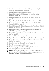
... processor. See "Installing an Expansion Card" on page 165 to the system board. 15 Replace the cooling shroud. NOTE: See "Running the System Diagnostics" on page 115. 14 Connect all the cables to verify that the new processor operates correctly. See "Installing the SAS Backplane" on page 111....Reattach any peripherals and connect the system to an electrical outlet. 20 Turn on page 87. 17 Close the system. See "Running the Embedded System Diagnostics" on page 129. 9 Replace the system fan. 5 Slide the system board toward the back of the system, inserting the connectors into the ...
... processor. See "Installing an Expansion Card" on page 165 to the system board. 15 Replace the cooling shroud. NOTE: See "Running the System Diagnostics" on page 115. 14 Connect all the cables to verify that the new processor operates correctly. See "Installing the SAS Backplane" on page 111....Reattach any peripherals and connect the system to an electrical outlet. 20 Turn on page 87. 17 Close the system. See "Running the Embedded System Diagnostics" on page 129. 9 Replace the system fan. 5 Slide the system board toward the back of the system, inserting the connectors into the ...
Hardware Owner's Manual
Page 148
... troubleshooting any external devices. See Figure 1-1 and Figure 1-3 for the front- Troubleshooting a USB Device 1 Use the following steps to the monitor. 3 Run the appropriate online diagnostic test. b Connect the keyboard/mouse to the external connectors on page 177. c Replace the keyboard/mouse with another working keyboard/mouse. If the tests fail... the keyboard and mouse cables from the system briefly and reconnect them from the system to troubleshoot a USB keyboard and/or mouse. See "Using Online Diagnostics" on page 165.
... troubleshooting any external devices. See Figure 1-1 and Figure 1-3 for the front- Troubleshooting a USB Device 1 Use the following steps to the monitor. 3 Run the appropriate online diagnostic test. b Connect the keyboard/mouse to the external connectors on page 177. c Replace the keyboard/mouse with another working keyboard/mouse. If the tests fail... the keyboard and mouse cables from the system briefly and reconnect them from the system to troubleshoot a USB keyboard and/or mouse. See "Using Online Diagnostics" on page 165.


