
Information Update - Power Infrastructure Sizing
Page 1
... characterized while using the power capping features enabled from Dell may result in 500W of power consumption for the configuration and workload, the 500W power value can be less efficient and more accurately approximate the appropriate size of the system to assess power consumption of Power Distribution Units (PDUs), Uninterruptible Power Supplies (UPSs), and other power infrastructure distribution equipment...
... characterized while using the power capping features enabled from Dell may result in 500W of power consumption for the configuration and workload, the 500W power value can be less efficient and more accurately approximate the appropriate size of the system to assess power consumption of Power Distribution Units (PDUs), Uninterruptible Power Supplies (UPSs), and other power infrastructure distribution equipment...

Getting Started Guide
Page 6
Securing the Power Cable(s) Bend the system power cable(s) into a grounded electrical outlet or a separate power source such as shown in the illustration and secure the cable(s) with the provided strap. Plug the other end of the power cable(s) into a loop as an uninterrupted power supply (UPS) or a power distribution unit (PDU). 4 Getting Started With Your System Connecting the Power Cable(s) Connect the system's power cable(s) to the system and, if a monitor is used, connect the monitor's power cable to the monitor.
Securing the Power Cable(s) Bend the system power cable(s) into a grounded electrical outlet or a separate power source such as shown in the illustration and secure the cable(s) with the provided strap. Plug the other end of the power cable(s) into a loop as an uninterrupted power supply (UPS) or a power distribution unit (PDU). 4 Getting Started With Your System Connecting the Power Cable(s) Connect the system's power cable(s) to the system and, if a monitor is used, connect the monitor's power cable to the monitor.
Getting Started Guide
Page 11
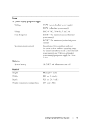
....5 inch) 23.5 kg (51.8 lb) Getting Started With Your System 9 Power AC power supply (per power supply) Wattage 375 W (non-redundant power supply) 400 W (redundant power supply) Voltage 100-240 VAC, 50/60 Hz, 5.8A-2.9A Heat dissipation 1683 BTU/hr maximum (non-redundant power supply) 1672 BTU/hr maximum (redundant power supply) Maximum inrush current Under typical line conditions and over the...
....5 inch) 23.5 kg (51.8 lb) Getting Started With Your System 9 Power AC power supply (per power supply) Wattage 375 W (non-redundant power supply) 400 W (redundant power supply) Voltage 100-240 VAC, 50/60 Hz, 5.8A-2.9A Heat dissipation 1683 BTU/hr maximum (non-redundant power supply) 1672 BTU/hr maximum (redundant power supply) Maximum inrush current Under typical line conditions and over the...

Hardware Owner's Manual
Page 6
... and Tape Drives 99 Removing an Optical or a Tape Drive 99 Installing an Optical or Tape Drive 100 Power Supplies 103 Removing a Redundant Power Supply 103 Installing a Redundant Power Supply 104 Removing a Non-Redundant Power Supply . . . 105 Installing a Non-Redundant Power Supply . . . . 106 System Fan 106 Removing the System Fan 106 Installing the System Fan 107 System Memory 108 6 Contents
... and Tape Drives 99 Removing an Optical or a Tape Drive 99 Installing an Optical or Tape Drive 100 Power Supplies 103 Removing a Redundant Power Supply 103 Installing a Redundant Power Supply 104 Removing a Non-Redundant Power Supply . . . 105 Installing a Non-Redundant Power Supply . . . . 106 System Fan 106 Removing the System Fan 106 Installing the System Fan 107 System Memory 108 6 Contents
Hardware Owner's Manual
Page 9
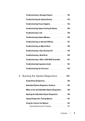
Troubleshooting a Damaged System 152 Troubleshooting the System Battery 152 Troubleshooting Power Supplies 153 Troubleshooting System Cooling Problems 154 Troubleshooting a Fan 154 Troubleshooting System Memory 155 Troubleshooting an Internal USB Key 157 Troubleshooting an Optical Drive 158 Troubleshooting a ...
Troubleshooting a Damaged System 152 Troubleshooting the System Battery 152 Troubleshooting Power Supplies 153 Troubleshooting System Cooling Problems 154 Troubleshooting a Fan 154 Troubleshooting System Memory 155 Troubleshooting an Internal USB Key 157 Troubleshooting an Optical Drive 158 Troubleshooting a ...
Hardware Owner's Manual
Page 13
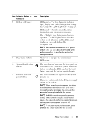
... Lights (Optional)" on indicator lights when the system power is turned off the system using the power button causes the system to perform a graceful shutdown before power to the system. Provides system ID, status information, and system error messages. The power button controls the DC power supply output to the system is on the front flashes...
... Lights (Optional)" on indicator lights when the system power is turned off the system using the power button causes the system to perform a graceful shutdown before power to the system. Provides system ID, status information, and system error messages. The power button controls the DC power supply output to the system is on the front flashes...
Hardware Owner's Manual
Page 20
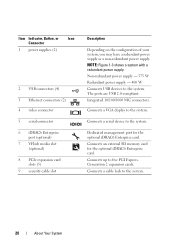
... to the system. Connects an external SD memory card for the optional iDRAC6 Enterprise card. Non-redundant power supply - 375 W Redundant power supply - 400 W Connects USB devices to the system. Integrated 10/100/1000 NIC connectors. Generation 2 expansion cards.... NOTE: Figure 1-3 shows a system with a redundant power supply. Connects a VGA display to the system. Item Indicator, Button, or Icon Connector 1 power supplies (2) 2 USB connectors (4) 3 Ethernet connectors (2) 4 video connector 5 serial connector 6 iDRAC6 Enterprise ...
... to the system. Connects an external SD memory card for the optional iDRAC6 Enterprise card. Non-redundant power supply - 375 W Redundant power supply - 400 W Connects USB devices to the system. Integrated 10/100/1000 NIC connectors. Generation 2 expansion cards.... NOTE: Figure 1-3 shows a system with a redundant power supply. Connects a VGA display to the system. Item Indicator, Button, or Icon Connector 1 power supplies (2) 2 USB connectors (4) 3 Ethernet connectors (2) 4 video connector 5 serial connector 6 iDRAC6 Enterprise ...

Hardware Owner's Manual
Page 22
... hot-adding a power supply, this indicates that the power supply is mismatched with the power supply. • Alternating green and amber - Indicates a problem with the other installed power supply. Replace the power supply that has the flashing indicator with a power supply that matches the capacity of the other power supply. AC power is providing DC power to the system. • Amber - Redundant Power Supply Status Indicator 1 1 power supply status indicator...
... hot-adding a power supply, this indicates that the power supply is mismatched with the power supply. • Alternating green and amber - Indicates a problem with the other installed power supply. Replace the power supply that has the flashing indicator with a power supply that matches the capacity of the other power supply. AC power is providing DC power to the system. • Amber - Redundant Power Supply Status Indicator 1 1 power supply status indicator...
Hardware Owner's Manual
Page 23
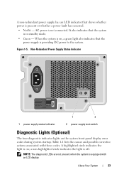
... - When the system is on, a green light also indicates that the system is providing DC power to the system. It also indicates that the power supply is in standby mode. • Green - Non-Redundant Power Supply Status Indicator 1 2 1 power supply status indicator 2 power supply test switch Diagnostic Lights (Optional) The four diagnostic indicator lights on ; About Your System 23...
... - When the system is on, a green light also indicates that the system is providing DC power to the system. It also indicates that the power supply is in standby mode. • Green - Non-Redundant Power Supply Status Indicator 1 2 1 power supply status indicator 2 power supply test switch Diagnostic Lights (Optional) The four diagnostic indicator lights on ; About Your System 23...
Hardware Owner's Manual
Page 30
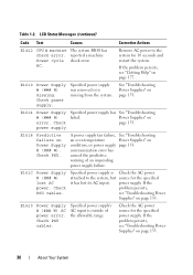
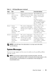
... Help" on page 153. 30 About Your System E161C Power Supply # (### W) lost its AC input. reported a machine Power cycle check error. A power supply fan failure, See "Troubleshooting an over-temperature Power Supplies" on Power Supply # (### W). Specified power supply was removed or is Check the AC power attached to the system for the specified power supply. power supply. Check PSU cables. If the problem persists, see "Troubleshooting...
... Help" on page 153. 30 About Your System E161C Power Supply # (### W) lost its AC input. reported a machine Power cycle check error. A power supply fan failure, See "Troubleshooting an over-temperature Power Supplies" on Power Supply # (### W). Specified power supply was removed or is Check the AC power attached to the system for the specified power supply. power supply. Check PSU cables. If the problem persists, see "Troubleshooting...
Hardware Owner's Manual
Page 31
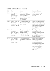
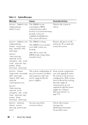
... clear the SEL. The system BIOS has reported an I /O channel check error. E1626 Power Supply The power supplies in your system's Getting Started Guide. PSU2 = ### W. than the power Check PSU and supplies can provide, config. About Your System 31 If the remaining power supply fails, the system will shut down. the system are installed. See the Technical Specifications...
... clear the SEL. The system BIOS has reported an I /O channel check error. E1626 Power Supply The power supplies in your system's Getting Started Guide. PSU2 = ### W. than the power Check PSU and supplies can provide, config. About Your System 31 If the remaining power supply fails, the system will shut down. the system are installed. See the Technical Specifications...
Hardware Owner's Manual
Page 39
... boot if throttled. Check PSU and system configuration. Turn off power to the system, reduce the hardware configuration or install higher-wattage power supplies, and then restart the system. Turn off power to the system, reduce the hardware configuration or install higher-wattage power supplies, and then restart the system. Table 1-2. See "Installing a RAID Battery" on...
... boot if throttled. Check PSU and system configuration. Turn off power to the system, reduce the hardware configuration or install higher-wattage power supplies, and then restart the system. Turn off power to the system, reduce the hardware configuration or install higher-wattage power supplies, and then restart the system. Table 1-2. See "Installing a RAID Battery" on...
Hardware Owner's Manual
Page 40
... exceeds PSU wattage. Continuing system boot accepts the risk that system may power down without this warning, then the replaced component(s) are not supported with this power supply. Alert! Table 1-3. Alert! Alert! If the system boots without warning. An error caused the system to boot. ...during previous boot. The iDRAC6 is not responding to reboot. Alert! Wait for possible causes. 40 About Your System Remove AC power to the previous configuration. Rebooting. If any system components were just upgraded, return the system to the system for 10 seconds and...
... exceeds PSU wattage. Continuing system boot accepts the risk that system may power down without this warning, then the replaced component(s) are not supported with this power supply. Alert! Table 1-3. Alert! Alert! If the system boots without warning. An error caused the system to boot. ...during previous boot. The iDRAC6 is not responding to reboot. Alert! Wait for possible causes. 40 About Your System Remove AC power to the previous configuration. Rebooting. If any system components were just upgraded, return the system to the system for 10 seconds and...
Hardware Owner's Manual
Page 53
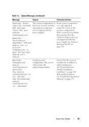
... PSU wattage. System will run but with this power supply. The memory configuration is : Invalid memory configuration. Performance degraded. CPU and memory set to minimum frequencies to the previous configuration. .... Table 1-3. Check PSU and system configuration. Warning! The system configuration of processor, memory modules, and expansion cards may not be supported by the power supplies. The system will reboot. See "General Memory Module Installation Guidelines" on page 108. The recommended memory configuration is not optimal. Warning! System Messages...
... PSU wattage. System will run but with this power supply. The memory configuration is : Invalid memory configuration. Performance degraded. CPU and memory set to minimum frequencies to the previous configuration. .... Table 1-3. Check PSU and system configuration. Warning! The system configuration of processor, memory modules, and expansion cards may not be supported by the power supplies. The system will reboot. See "General Memory Module Installation Guidelines" on page 108. The recommended memory configuration is not optimal. Warning! System Messages...
Hardware Owner's Manual
Page 79
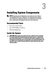
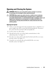
...swappable hard drives and an LCD panel. Installing System Components 79 Read and follow the safety instructions that is not authorized by Dell is not covered by your warranty. You should only perform troubleshooting and simple repairs as authorized in this section show a system...screwdrivers • Wrist grounding strap Inside the System CAUTION: Many repairs may have cabled or hot-swappable hard drives, redundant or non-redundant power supplies, and an LCD panel or diagnostic indicators. Installing System Components NOTE: Depending on the configuration, your system may only be done by a...
...swappable hard drives and an LCD panel. Installing System Components 79 Read and follow the safety instructions that is not authorized by Dell is not covered by your warranty. You should only perform troubleshooting and simple repairs as authorized in this section show a system...screwdrivers • Wrist grounding strap Inside the System CAUTION: Many repairs may have cabled or hot-swappable hard drives, redundant or non-redundant power supplies, and an LCD panel or diagnostic indicators. Installing System Components NOTE: Depending on the configuration, your system may only be done by a...

Hardware Owner's Manual
Page 80
Inside the System 1 12 11 10 9 2 3 4 8 5 7 6 1 system cover 3 system cooling fan 5 heat sink and processor 7 SAS backplane 9 optical drive 11 power supplies 2 cooling shroud 4 expansion card slots (5) 6 memory modules (6) 8 hard drives (4) 10 power distribution board 12 power supply bays (2) 80 Installing System Components Figure 3-1.
Inside the System 1 12 11 10 9 2 3 4 8 5 7 6 1 system cover 3 system cooling fan 5 heat sink and processor 7 SAS backplane 9 optical drive 11 power supplies 2 cooling shroud 4 expansion card slots (5) 6 memory modules (6) 8 hard drives (4) 10 power distribution board 12 power supply bays (2) 80 Installing System Components Figure 3-1.
Hardware Owner's Manual
Page 85
... 1 Unless you are removing a hot-swap component such as directed by a certified service technician. Read and follow the safety instructions that is not authorized by Dell is not covered by your product documentation, or as a hard drive or a power supply, turn off the system and attached peripherals.
... 1 Unless you are removing a hot-swap component such as directed by a certified service technician. Read and follow the safety instructions that is not authorized by Dell is not covered by your product documentation, or as a hard drive or a power supply, turn off the system and attached peripherals.
Hardware Owner's Manual
Page 103
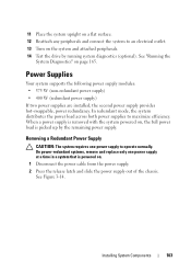
... attached peripherals. 14 Test the drive by the remaining power supply. On power-redundant systems, remove and replace only one power supply to operate normally. Power Supplies Your system supports the following power supply modules: • 375 W (non-redundant power supply) • 400 W (redundant power supply) If two power supplies are installed, the second power supply provides hot-swappable, power redundancy. 11 Place the system upright on a flat...
... attached peripherals. 14 Test the drive by the remaining power supply. On power-redundant systems, remove and replace only one power supply to operate normally. Power Supplies Your system supports the following power supply modules: • 375 W (non-redundant power supply) • 400 W (redundant power supply) If two power supplies are installed, the second power supply provides hot-swappable, power redundancy. 11 Place the system upright on a flat...
Hardware Owner's Manual
Page 104
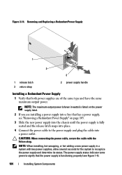
... Replacing a Redundant Power Supply 1 2 3 1 release latch 3 velcro strap 2 power supply handle Installing a Redundant Power Supply 1 Verify that has a power supply, see Figure 1-4). 104 Installing System Components The power-supply status indicator turns green to signify that the power supply is functioning properly (see "Removing a Redundant Power Supply" on page 103. 3 Slide the new power supply into the chassis until the power supply is listed on the power supply label. 2 If...
... Replacing a Redundant Power Supply 1 2 3 1 release latch 3 velcro strap 2 power supply handle Installing a Redundant Power Supply 1 Verify that has a power supply, see Figure 1-4). 104 Installing System Components The power-supply status indicator turns green to signify that the power supply is functioning properly (see "Removing a Redundant Power Supply" on page 103. 3 Slide the new power supply into the chassis until the power supply is listed on the power supply label. 2 If...
Hardware Owner's Manual
Page 105
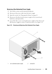
See Figure 3-15. See "Opening the System" on page 85. 4 Disconnect all attached peripherals. 2 Disconnect the power cable from the chassis. Removing and Replacing a Non-Redundant Power Supply 1 2 1 non-redundant power supply 2 screws (3) Installing System Components 105 Figure 3-15. Removing a Non-Redundant Power Supply 1 Turn off the system and all cables from the power supply to the system board, hard drives and optical drive. 5 Loosen the three screws securing the power supply to the chassis and lift the power supply to remove it from the power supply. 3 Open the system.
See Figure 3-15. See "Opening the System" on page 85. 4 Disconnect all attached peripherals. 2 Disconnect the power cable from the chassis. Removing and Replacing a Non-Redundant Power Supply 1 2 1 non-redundant power supply 2 screws (3) Installing System Components 105 Figure 3-15. Removing a Non-Redundant Power Supply 1 Turn off the system and all cables from the power supply to the system board, hard drives and optical drive. 5 Loosen the three screws securing the power supply to the chassis and lift the power supply to remove it from the power supply. 3 Open the system.


