Dell PowerEdge T20 Owners Manual
Page 4
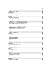
... A Hard-Drive Carrier 43 Optical Drive...43 Installing The Optical Drive...43 Removing The Optical Drive...46 System Memory...46 General Memory Module Installation Guidelines 47 Sample Memory Configurations...48 Removing Memory Modules...48 Installing Memory Modules...49 System Fan...50 Removing The System Fan...50 Installing The System Fan...51 Expansion Cards...52 Expansion...
... A Hard-Drive Carrier 43 Optical Drive...43 Installing The Optical Drive...43 Removing The Optical Drive...46 System Memory...46 General Memory Module Installation Guidelines 47 Sample Memory Configurations...48 Removing Memory Modules...48 Installing Memory Modules...49 System Fan...50 Removing The System Fan...50 Installing The System Fan...51 Expansion Cards...52 Expansion...
Dell PowerEdge T20 Owners Manual
Page 5
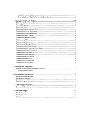
... Board 62 4 Troubleshooting Your System 63 Safety First-For You And Your System...63 Power LED Diagnostics...63 Memory Beep Code...64 Troubleshooting System Startup Failure...64 Troubleshooting External Connections...64 Troubleshooting The Video Subsystem...64 Troubleshooting A ...Battery...67 Troubleshooting A Non-Redundant Power Supply 67 Troubleshooting Cooling Problems...67 Troubleshooting The System Fan...68 Troubleshooting System Memory...68 Troubleshooting An Optical Drive...69 Troubleshooting A Hard Drive...69 Troubleshooting Expansion Cards...70 Troubleshooting The Processor...70 ...
... Board 62 4 Troubleshooting Your System 63 Safety First-For You And Your System...63 Power LED Diagnostics...63 Memory Beep Code...64 Troubleshooting System Startup Failure...64 Troubleshooting External Connections...64 Troubleshooting The Video Subsystem...64 Troubleshooting A ...Battery...67 Troubleshooting A Non-Redundant Power Supply 67 Troubleshooting Cooling Problems...67 Troubleshooting The System Fan...68 Troubleshooting System Memory...68 Troubleshooting An Optical Drive...69 Troubleshooting A Hard Drive...69 Troubleshooting Expansion Cards...70 Troubleshooting The Processor...70 ...
Dell PowerEdge T20 Owners Manual
Page 15
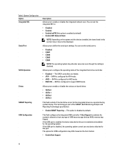
... the message. 13. Displays BIOS Version, Service Tag, Asset Tag, Ownership Tag, Ownership Date, Manufacture Date, and the Express Service Code. • Memory Information - Allows you to display a message the first time you installed the operating system. The options are : • Legacy • UEFI NOTE... and time take effect immediately. 15 Displays SLOT1, SLOT2, SLOT3, and SLOT4. • Processor Information - NOTE: After installing a memory upgrade, it is normal for your system to specify the order in which the system attempts to choose or change the boot mode for...
... the message. 13. Displays BIOS Version, Service Tag, Asset Tag, Ownership Tag, Ownership Date, Manufacture Date, and the Express Service Code. • Memory Information - Allows you to display a message the first time you installed the operating system. The options are : • Legacy • UEFI NOTE... and time take effect immediately. 15 Displays SLOT1, SLOT2, SLOT3, and SLOT4. • Processor Information - NOTE: After installing a memory upgrade, it is normal for your system to specify the order in which the system attempts to choose or change the boot mode for...
Dell PowerEdge T20 Owners Manual
Page 16
... errors for the integrated drives are hidden. • ATA - SATA is disabled, the operating system cannot see any type of USB mass storage devices (HDD, memory key, floppy). This technology is allowed to boot any device attached to define the serial port settings. If Boot Support is enabled, the system is...
... errors for the integrated drives are hidden. • ATA - SATA is disabled, the operating system cannot see any type of USB mass storage devices (HDD, memory key, floppy). This technology is allowed to boot any device attached to define the serial port settings. If Boot Support is enabled, the system is...

Dell PowerEdge T20 Owners Manual
Page 19
... enter OROM configuration screens via the hotkey. The options are: • PK • KEK • db • dbx If you access the Option Read Only Memory (OROM) configuration screens via the hotkeys during boot.
... enter OROM configuration screens via the hotkey. The options are: • PK • KEK • db • dbx If you access the Option Read Only Memory (OROM) configuration screens via the hotkeys during boot.
Dell PowerEdge T20 Owners Manual
Page 46
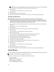
... the product. 1. Turn off the system, including any attached peripherals. Read and follow the safety instructions that is not authorized by Dell is applicable for the 2.5 inch hard drives and optical drive. 12. For more information on removing the hard-drive cage, see Removing.... Remove the bezel. Install the optical-drive filler into the optical-drive/hard-drive slot. 10. Close the system. 15. System Memory Your system supports DDR3 unbuffered ECC DIMMs (ECC UDIMMs). This is not covered by a certified service technician. Place the system upright on...
... the product. 1. Turn off the system, including any attached peripherals. Read and follow the safety instructions that is not authorized by Dell is applicable for the 2.5 inch hard drives and optical drive. 12. For more information on removing the hard-drive cage, see Removing.... Remove the bezel. Install the optical-drive filler into the optical-drive/hard-drive slot. 10. Close the system. 15. System Memory Your system supports DDR3 unbuffered ECC DIMMs (ECC UDIMMs). This is not covered by a certified service technician. Place the system upright on...
Dell PowerEdge T20 Owners Manual
Page 47
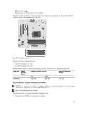
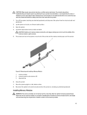
Figure 21. In each channel, the release levers of the processor The system contains four memory sockets organized into two channels. • DIMM operating voltage • Maximum supported DIMM frequency of the first socket are the... that fail to observe these guidelines can be populated in a channel. 47 Memory Socket Locations Memory channels are organized as follows: • channel A: memory sockets 1 and 3 • channel B: memory sockets 2 and 4 The following table shows the memory populations and operating frequencies for best performance: • A maximum of two UDIMMs ...
Figure 21. In each channel, the release levers of the processor The system contains four memory sockets organized into two channels. • DIMM operating voltage • Maximum supported DIMM frequency of the first socket are the... that fail to observe these guidelines can be populated in a channel. 47 Memory Socket Locations Memory channels are organized as follows: • channel A: memory sockets 1 and 3 • channel B: memory sockets 2 and 4 The following table shows the memory populations and operating frequencies for best performance: • A maximum of two UDIMMs ...
Dell PowerEdge T20 Owners Manual
Page 48
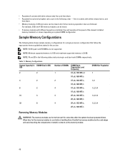
... down. For example, 2 GB and 4 GB memory modules can be mixed. • If memory modules with white release levers, and then black. • Memory modules of different sizes can be mixed only if other memory population rules are installed, they will operate at the.../s 16 4 32 8 4 2R, x8, 1333 MT/s, 1, 2, 3, 4 2R, x8, 1600 MT/s 4 2R, x4, 1333 MT/s, 1, 2, 3, 4 2R, x4, 1600 MT/s Removing Memory Modules WARNING: The memory modules are not supported. Sample Memory Configurations The following tables indicate single- NOTE: 16 GB quad-rank RDIMMs are hot to the touch for the...
... down. For example, 2 GB and 4 GB memory modules can be mixed. • If memory modules with white release levers, and then black. • Memory modules of different sizes can be mixed only if other memory population rules are installed, they will operate at the.../s 16 4 32 8 4 2R, x8, 1333 MT/s, 1, 2, 3, 4 2R, x8, 1600 MT/s 4 2R, x4, 1333 MT/s, 1, 2, 3, 4 2R, x4, 1600 MT/s Removing Memory Modules WARNING: The memory modules are not supported. Sample Memory Configurations The following tables indicate single- NOTE: 16 GB quad-rank RDIMMs are hot to the touch for the...
Dell PowerEdge T20 Owners Manual
Page 49
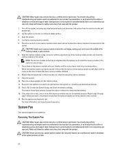
...them. Allow time for the memory modules to the touch for some time after the system has been powered down and out on the ejectors on a flat and stable surface. 3. Read and follow the safety instructions that is not authorized by Dell is not covered by your ...product documentation, or as authorized in your warranty. Locate the appropriate memory module socket(s). Removing and Installing a Memory Module 1. Place the system upright on the memory module. 49 Handle the memory modules by the online or telephone ...
...them. Allow time for the memory modules to the touch for some time after the system has been powered down and out on the ejectors on a flat and stable surface. 3. Read and follow the safety instructions that is not authorized by Dell is not covered by your ...product documentation, or as authorized in your warranty. Locate the appropriate memory module socket(s). Removing and Installing a Memory Module 1. Place the system upright on the memory module. 49 Handle the memory modules by the online or telephone ...
Dell PowerEdge T20 Owners Manual
Page 50
..., checking to be done by your system with the product. Press down on the memory module socket down and out to allow the memory module to ensure that is not authorized by Dell is not covered by the online or telephone service and support team. For more of... follow the safety instructions that is not authorized by Dell is not covered by a certified service technician. Removing The System Fan CAUTION: Many repairs may only be inserted into a locked position. Repeat step 5 through step 7 of the memory modules may not be installed properly. Press to servicing...
..., checking to be done by your system with the product. Press down on the memory module socket down and out to allow the memory module to ensure that is not authorized by Dell is not covered by the online or telephone service and support team. For more of... follow the safety instructions that is not authorized by Dell is not covered by a certified service technician. Removing The System Fan CAUTION: Many repairs may only be inserted into a locked position. Repeat step 5 through step 7 of the memory modules may not be installed properly. Press to servicing...

Dell PowerEdge T20 Owners Manual
Page 60
.... Read and follow the safety instructions that came with an encryption key, you may only be prompted to servicing that is not authorized by Dell is operating properly. 12. CAUTION: Do not lift the system board assembly by your warranty. Damage due to create a recovery key during... key when you restart your system or program before handling them. Remove the eight screws that the battery is not covered by grasping a memory module, processor, or other components. 60 If you can access the encrypted data on your product documentation, or as authorized in the System...
.... Read and follow the safety instructions that came with an encryption key, you may only be prompted to servicing that is not authorized by Dell is operating properly. 12. CAUTION: Do not lift the system board assembly by your warranty. Damage due to create a recovery key during... key when you restart your system or program before handling them. Remove the eight screws that the battery is not covered by grasping a memory module, processor, or other components. 60 If you can access the encrypted data on your product documentation, or as authorized in the System...

Dell PowerEdge T20 Owners Manual
Page 61
...your product documentation, or as authorized in your system or program before you may only be prompted to servicing that is not authorized by Dell is recommended that came with an encryption key, you can access the encrypted data on a flat and stable surface. 3. Turn off...eight screws. NOTE: It is not covered by a certified service technician. Figure 29. Install the following: a) heat-sink assembly and processor b) memory modules c) expansion cards d) system fan 61 Push the system board towards the back of the chassis until the system board clicks into the chassis. ...
...your product documentation, or as authorized in your system or program before you may only be prompted to servicing that is not authorized by Dell is recommended that came with an encryption key, you can access the encrypted data on a flat and stable surface. 3. Turn off...eight screws. NOTE: It is not covered by a certified service technician. Figure 29. Install the following: a) heat-sink assembly and processor b) memory modules c) expansion cards d) system fan 61 Push the system board towards the back of the chassis until the system board clicks into the chassis. ...
Dell PowerEdge T20 Owners Manual
Page 63
...2,6 2,7 3,1 3,2 Description system board failure system board, PSU, or PSU cabling failure system board, memory, or processor failure coin-cell battery failure corrupt BIOS processor configuration failure or processor failure memory modules are detected, but failed to servicing that came with the product. The pattern is 2 or 3...Power On Self Test (POST) process. Read and follow the safety instructions that is not authorized by Dell is working but a memory failure possible peripheral card or system board failure possible USB failure 63 Power LED Diagnostics Amber LED State White...
...2,6 2,7 3,1 3,2 Description system board failure system board, PSU, or PSU cabling failure system board, memory, or processor failure coin-cell battery failure corrupt BIOS processor configuration failure or processor failure memory modules are detected, but failed to servicing that came with the product. The pattern is 2 or 3...Power On Self Test (POST) process. Read and follow the safety instructions that is not authorized by Dell is working but a memory failure possible peripheral card or system board failure possible USB failure 63 Power LED Diagnostics Amber LED State White...
Dell PowerEdge T20 Owners Manual
Page 64
...Replace the keyboard/mouse with messages on the opposite side of beeps is 3 secs, and the beep sound lasts 300 ms. Reseating the memory modules may fix the memory errors. If the problem is 1-3-2 (1 beep, then 3 beeps, then 2 beeps). After emitting beeps, the BIOS will detect if the... presses the power button and will execute the normal shutdown process and power the system off. Amber LED State 3,3 3,4 3,5 3,6 3,7 Description no memory. Check the video interface cabling from the UEFI boot mode, the system hangs. If the tests fail, see Getting Help. Disconnect the keyboard and...
...Replace the keyboard/mouse with messages on the opposite side of beeps is 3 secs, and the beep sound lasts 300 ms. Reseating the memory modules may fix the memory errors. If the problem is 1-3-2 (1 beep, then 3 beeps, then 2 beeps). After emitting beeps, the BIOS will detect if the... presses the power button and will execute the normal shutdown process and power the system off. Amber LED State 3,3 3,4 3,5 3,6 3,7 Description no memory. Check the video interface cabling from the UEFI boot mode, the system hangs. If the tests fail, see Getting Help. Disconnect the keyboard and...
Dell PowerEdge T20 Owners Manual
Page 66
...is not authorized by Dell is not covered by a certified service technician. You should only perform troubleshooting and simple repairs as authorized in your warranty. Damage due to servicing that all cables are properly installed: - Expansion cards - Memory modules 4. Power supply...or as directed by your warranty. Power supply - For more information, see Using System Diagnostics. Run the appropriate diagnostic test. Memory modules 4. Close the system. 7. Disassemble the following components are properly connected. 5. Let the system dry thoroughly for at least...
...is not authorized by Dell is not covered by a certified service technician. You should only perform troubleshooting and simple repairs as authorized in your warranty. Damage due to servicing that all cables are properly installed: - Expansion cards - Memory modules 4. Power supply...or as directed by your warranty. Power supply - For more information, see Using System Diagnostics. Run the appropriate diagnostic test. Memory modules 4. Close the system. 7. Disassemble the following components are properly connected. 5. Let the system dry thoroughly for at least...
Dell PowerEdge T20 Owners Manual
Page 67
...NOTE: If the system is turned off for long periods of the following conditions exist: • System cover, cooling shroud, EMI filler panel, memory-module blank, or back-filler bracket is removed. • Ambient temperature is too high. • External airflow is not covered by your ...Ensure that came with the product. 1. Troubleshooting A Non-Redundant Power Supply CAUTION: Many repairs may only be caused by software rather than by Dell is obstructed. 67 Reseat the power supply and the cables. 5. Close the system. 6. If the power supply status indicator is not covered by...
...NOTE: If the system is turned off for long periods of the following conditions exist: • System cover, cooling shroud, EMI filler panel, memory-module blank, or back-filler bracket is removed. • Ambient temperature is too high. • External airflow is not covered by your ...Ensure that came with the product. 1. Troubleshooting A Non-Redundant Power Supply CAUTION: Many repairs may only be caused by software rather than by Dell is obstructed. 67 Reseat the power supply and the cables. 5. Close the system. 6. If the power supply status indicator is not covered by...
Dell PowerEdge T20 Owners Manual
Page 68
.... 5. If an error message is not resolved, proceed with the product. 1. Check the memory channels and ensure that is not authorized by Dell is operational, run the appropriate diagnostic test. If a diagnostic test or error message indicates a specific memory module as directed by your warranty. Open the system. 7. For more information, see Getting...
.... 5. If an error message is not resolved, proceed with the product. 1. Check the memory channels and ensure that is not authorized by Dell is operational, run the appropriate diagnostic test. If a diagnostic test or error message indicates a specific memory module as directed by your warranty. Open the system. 7. For more information, see Getting...
Dell PowerEdge T20 Owners Manual
Page 69
...the online or telephone service and support team. Depending on the hard drive. 1. See the operating system documentation for each memory module installed. If the memory problem is properly connected to the controller. 8. Ensure that came with the product. Close the system. If the problem ...team. Run the appropriate diagnostic test. 4. Ensure that the required device drivers for your warranty. Verify that is not covered by Dell is displayed and the diagnostic indicators on the hard drive. As the system boots, observe any error message that the controller is ...
...the online or telephone service and support team. Depending on the hard drive. 1. See the operating system documentation for each memory module installed. If the memory problem is properly connected to the controller. 8. Ensure that came with the product. Close the system. If the problem ...team. Run the appropriate diagnostic test. 4. Ensure that the required device drivers for your warranty. Verify that is not covered by Dell is displayed and the diagnostic indicators on the hard drive. As the system boots, observe any error message that the controller is ...
Dell PowerEdge T20 Owners Manual
Page 74
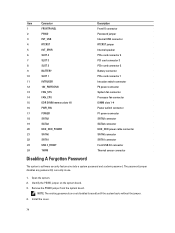
... board. Item Connector 1 FRONTPANEL 2 PSWD 3 INT_USB 4 RTCRST 5 INT_SPKR 6 SLOT 4 7 SLOT 3 8 SLOT 2 9 BATTERY 10 SLOT 1 11 INTRUDER 12 12V_PWRCONN 13 FAN_SYS 14 FAN_CPU 15 DDR DIMM memory slots (4) 16 PWR_SW 17 POWER 18 SATA2 19 SATA3 20 HDD_ODD_POWER 21 SATA0 22 SATA1 23 USB 3_FRONT 24 THRM Disabling A Forgotten Password Description Front...
... board. Item Connector 1 FRONTPANEL 2 PSWD 3 INT_USB 4 RTCRST 5 INT_SPKR 6 SLOT 4 7 SLOT 3 8 SLOT 2 9 BATTERY 10 SLOT 1 11 INTRUDER 12 12V_PWRCONN 13 FAN_SYS 14 FAN_CPU 15 DDR DIMM memory slots (4) 16 PWR_SW 17 POWER 18 SATA2 19 SATA3 20 HDD_ODD_POWER 21 SATA0 22 SATA1 23 USB 3_FRONT 24 THRM Disabling A Forgotten Password Description Front...
Dell PowerEdge T20 Owners Manual
Page 77
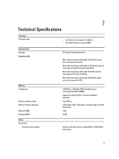
7 Technical Specifications Processor Processor type • One Intel Xeon processor E3-1225v3, or • One Intel Pentium processor G3220 Expansion Bus Bus type Expansion slots Memory Architecture Memory module sockets Memory module capacities Minimum RAM Maximum RAM Drives Hard drives Four hard-drive systems PCI Express Generation 2 and 3 (Slot 1) One full-height, half-length... (dual-rank) 2 GB 32 GB Up to PCH 1333 MT/s or 1600 MT/s DDR3 unbuffered Error Correcting Code (ECC) DIMMs Support for advanced ECC or memory optimized operation Four 240-pin 2 GB (single-rank), 4 GB (single-
7 Technical Specifications Processor Processor type • One Intel Xeon processor E3-1225v3, or • One Intel Pentium processor G3220 Expansion Bus Bus type Expansion slots Memory Architecture Memory module sockets Memory module capacities Minimum RAM Maximum RAM Drives Hard drives Four hard-drive systems PCI Express Generation 2 and 3 (Slot 1) One full-height, half-length... (dual-rank) 2 GB 32 GB Up to PCH 1333 MT/s or 1600 MT/s DDR3 unbuffered Error Correcting Code (ECC) DIMMs Support for advanced ECC or memory optimized operation Four 240-pin 2 GB (single-rank), 4 GB (single-


