Getting Started Guide
Page 5
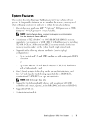
... hardware and software features of your system and how to obtain technical assistance. • One dual-core or quad-core AMD™ Opteron™ 1000 processor or AMD Sempron™ W/ECC processor (when available). or 800-MHz DDR II SDRAM memory, upgradable to a maximum of 667- Up to view...
... hardware and software features of your system and how to obtain technical assistance. • One dual-core or quad-core AMD™ Opteron™ 1000 processor or AMD Sempron™ W/ECC processor (when available). or 800-MHz DDR II SDRAM memory, upgradable to a maximum of 667- Up to view...
Getting Started Guide
Page 10
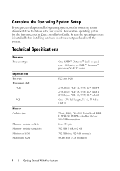
or quadcore 1000 series or AMD™ Sempron™ processor, W/ECC series. To install an operating system for 667- Technical Specifications Processor Processor type Expansion Bus Bus type Expansion slots PCIe PCI Memory Architecture Memory module sockets Memory module capacities Minimum RAM Maximum RAM One AMD™ Opteron&#...
or quadcore 1000 series or AMD™ Sempron™ processor, W/ECC series. To install an operating system for 667- Technical Specifications Processor Processor type Expansion Bus Bus type Expansion slots PCIe PCI Memory Architecture Memory module sockets Memory module capacities Minimum RAM Maximum RAM One AMD™ Opteron&#...
Hardware Owner's Manual (PDF)
Page 5
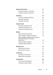
... With 8-GB Configurations (Microsoft® Windows® Operating System Only 76 Removing a Memory Module 77 Installing a Memory Module 77 Microprocessor 79 Removing the Processor 79 Replacing the Processor 82 Cooling Fans 83 Removing the Cooling Fans 84 Replacing the Cooling Fans 86 System Battery 88 Removing the System Battery 89 Installing the...
... With 8-GB Configurations (Microsoft® Windows® Operating System Only 76 Removing a Memory Module 77 Installing a Memory Module 77 Microprocessor 79 Removing the Processor 79 Replacing the Processor 82 Cooling Fans 83 Removing the Cooling Fans 84 Replacing the Cooling Fans 86 System Battery 88 Removing the System Battery 89 Installing the...

Hardware Owner's Manual (PDF)
Page 18
.... If the power LED shows a solid amber, a BIOS failure occurred before Power-On Self Test (POST). The diagnostic lights are not lit after POST. Possible processor failure. See "Troubleshooting System Memory" on ; Table 1-5. has occurred. Table 1-5 lists the causes and possible corrective actions associated with the power supply. A highlighted circle indicates...
.... If the power LED shows a solid amber, a BIOS failure occurred before Power-On Self Test (POST). The diagnostic lights are not lit after POST. Possible processor failure. See "Troubleshooting System Memory" on ; Table 1-5. has occurred. Table 1-5 lists the causes and possible corrective actions associated with the power supply. A highlighted circle indicates...

Hardware Owner's Manual (PDF)
Page 21
...last time the system was used. See "Microprocessor" on send data to respond Bad command or file name Causes Corrective Actions Use only Dell supported processors. The fan caused errors the last time the system was used the correct pathname. Ensure that nothing is blocking the airflow vents and ...that the processor heat sink is blocking the airflow vents and that you have spelled the command correctly, have put spaces in the proper place, and have...
...last time the system was used. See "Microprocessor" on send data to respond Bad command or file name Causes Corrective Actions Use only Dell supported processors. The fan caused errors the last time the system was used the correct pathname. Ensure that nothing is blocking the airflow vents and ...that the processor heat sink is blocking the airflow vents and that you have spelled the command correctly, have put spaces in the proper place, and have...

Hardware Owner's Manual (PDF)
Page 23
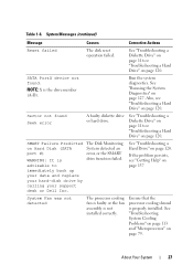
.... If the diskette-drive indicator turns on page 116. Take the appropriate action to resolve the problem. Ensure that the processor cooling shroud is writeprotected. See "Troubleshooting System Cooling Problems" on page 113 and "Microprocessor" on page 128. information might be loose.... drive. The processor cooling fan is faulty or the fan assembly is in the Insert a diskette in the drive. System Messages (continued) Message Diskette...
.... If the diskette-drive indicator turns on page 116. Take the appropriate action to resolve the problem. Ensure that the processor cooling shroud is writeprotected. See "Troubleshooting System Cooling Problems" on page 113 and "Microprocessor" on page 128. information might be loose.... drive. The processor cooling fan is faulty or the fan assembly is in the Insert a diskette in the drive. System Messages (continued) Message Diskette...
Hardware Owner's Manual (PDF)
Page 27
...drive or hard drive. SMART Failure Predicted on page 137 System Fan was not detected The processor cooling fan is faulty or the fan assembly is the drive number (A-D). Ensure that the processor cooling shroud is advisable to immediately back up your data and replace your hard-disk drive... by calling your support desk or Dell Inc. See "Troubleshooting System Cooling Problems" on page 113 and "Microprocessor" on...
...drive or hard drive. SMART Failure Predicted on page 137 System Fan was not detected The processor cooling fan is faulty or the fan assembly is the drive number (A-D). Ensure that the processor cooling shroud is advisable to immediately back up your data and replace your hard-disk drive... by calling your support desk or Dell Inc. See "Troubleshooting System Cooling Problems" on page 113 and "Microprocessor" on...

Hardware Owner's Manual (PDF)
Page 34
.... NOTE: The options for security devices. Main System Options Option Description System Time Resets the time on page 35. CPU Information Displays information for the processor installed in which the system searches for each group of information fields that the boot device is as hard drive, CD drive, or DVD drive...
.... NOTE: The options for security devices. Main System Options Option Description System Time Resets the time on page 35. CPU Information Displays information for the processor installed in which the system searches for each group of information fields that the boot device is as hard drive, CD drive, or DVD drive...

Hardware Owner's Manual (PDF)
Page 36
... system. When set to Enabled, the CPU Performance State Tables are also unchoosable. Displays the family and model number of the processor. This option does not have user-selectable settings. CPU Information Screen Table 2-4 lists the options and descriptions for the information fields...option does not have user-selectable settings. Table 2-4. CPU Information Screen Option 64-Bit Core Speed Bus Speed Demand-Based Power Management Processor 1 ID Level2 Cache Number of cores in the system, the SATA Configuration screen changes. This option does not have user-selectable ...
... system. When set to Enabled, the CPU Performance State Tables are also unchoosable. Displays the family and model number of the processor. This option does not have user-selectable settings. CPU Information Screen Table 2-4 lists the options and descriptions for the information fields...option does not have user-selectable settings. Table 2-4. CPU Information Screen Option 64-Bit Core Speed Bus Speed Demand-Based Power Management Processor 1 ID Level2 Cache Number of cores in the system, the SATA Configuration screen changes. This option does not have user-selectable ...

Hardware Owner's Manual (PDF)
Page 46
... board 5 3.5-inch drive bay 7 5.25-inch drive bays (2) 9 drive cage 4 2 heat sink and shroud assembly 4 hard drives (2) 6 tape backup unit 8 bezel sliding plate release 10 processor cooling fan The system board can accommodate one processor, four expansion cards, and four memory modules.
... board 5 3.5-inch drive bay 7 5.25-inch drive bays (2) 9 drive cage 4 2 heat sink and shroud assembly 4 hard drives (2) 6 tape backup unit 8 bezel sliding plate release 10 processor cooling fan The system board can accommodate one processor, four expansion cards, and four memory modules.

Hardware Owner's Manual (PDF)
Page 75
... memory upgrade kits from Dell. It is upgradable to 8 GB by installing combinations of matched memory size, speed, and technology. • Memory modules must be installed in ordered pairs in connectors DIMM_1 and DIMM_2, and then DIMM_3 and DIMM_4. • If a processor with a slower front-...memory module is installed, it in the proper slots according to the configuration guidelines in the wrong slots will operate at the processor's slower front-side bus speed. Memory Module Upgrade Kits The system is important to follow the slot installation configurations shown here...
... memory upgrade kits from Dell. It is upgradable to 8 GB by installing combinations of matched memory size, speed, and technology. • Memory modules must be installed in ordered pairs in connectors DIMM_1 and DIMM_2, and then DIMM_3 and DIMM_4. • If a processor with a slower front-...memory module is installed, it in the proper slots according to the configuration guidelines in the wrong slots will operate at the processor's slower front-side bus speed. Memory Module Upgrade Kits The system is important to follow the slot installation configurations shown here...

Hardware Owner's Manual (PDF)
Page 79
... is correct, press to exit the System Setup program. 14 Run the system diagnostics to reflect the newly installed memory. Removing the Processor CAUTION: Only trained service technicians are seated properly in a 939-pin micro pin grid array (PGA) package. See "Running the System... of the components inside the computer and protecting against electrostatic discharge. See "Opening the System" on the system and attached peripherals. The processor and its associated internal cache memory are operating properly. See "System Setup Options" on page 128. The system should have changed ....
... is correct, press to exit the System Setup program. 14 Run the system diagnostics to reflect the newly installed memory. Removing the Processor CAUTION: Only trained service technicians are seated properly in a 939-pin micro pin grid array (PGA) package. See "Running the System... of the components inside the computer and protecting against electrostatic discharge. See "Opening the System" on the system and attached peripherals. The processor and its associated internal cache memory are operating properly. See "System Setup Options" on page 128. The system should have changed ....

Hardware Owner's Manual (PDF)
Page 80
... System Components See Figure 3-21. 5 Tilt the heat sink and shroud assembly away from the electrical outlet. 2 Open the system. CAUTION: The processor and heat sink can get very hot during normal operation. See "Opening the System" on page 47. 3 Detach the diskette cable that they have... had sufficient time to the processor cooling fan housing. Ensure that is braced on its pivot bracket and lift it aside. 4 Using a #2 Phillips screwdriver, loosen the two captive ...
... System Components See Figure 3-21. 5 Tilt the heat sink and shroud assembly away from the electrical outlet. 2 Open the system. CAUTION: The processor and heat sink can get very hot during normal operation. See "Opening the System" on page 47. 3 Detach the diskette cable that they have... had sufficient time to the processor cooling fan housing. Ensure that is braced on its pivot bracket and lift it aside. 4 Using a #2 Phillips screwdriver, loosen the two captive ...

Hardware Owner's Manual (PDF)
Page 81
Installing and Removing the Heat Sink 1 2 3 1 heat sink and shroud assembly 3 captive screws (2) 4 2 pivot bracket 4 diskette cable 6 Open the processor cover by sliding the release lever from under the release lever latch on the socket. Installing System Components 81 Then, pull the lever back until it is vertically straight to release the processor. Figure 3-21. See Figure 3-22.
Installing and Removing the Heat Sink 1 2 3 1 heat sink and shroud assembly 3 captive screws (2) 4 2 pivot bracket 4 diskette cable 6 Open the processor cover by sliding the release lever from under the release lever latch on the socket. Installing System Components 81 Then, pull the lever back until it is vertically straight to release the processor. Figure 3-21. See Figure 3-22.

Hardware Owner's Manual (PDF)
Page 82
... arrow indicator on the system board. Replacing the Processor 1 Unpack the new processor. 2 Ensure that the contacts on the socket connector pads. 7 Lift the processor straight up and out of the replacement processor so that it points in the release position so.... See Figure 3-22. 82 Installing System Components NOTICE: Be careful not to the processor's delicate connections. Installing and Removing a Processor 1 4 2 3 1 pin 1 marker 3 socket 2 release lever 4 processor NOTICE: Do not pry the processor from dirt or other foreign material. 3 Align the pin 1 marker of the socket...
... arrow indicator on the system board. Replacing the Processor 1 Unpack the new processor. 2 Ensure that the contacts on the socket connector pads. 7 Lift the processor straight up and out of the replacement processor so that it points in the release position so.... See Figure 3-22. 82 Installing System Components NOTICE: Be careful not to the processor's delicate connections. Installing and Removing a Processor 1 4 2 3 1 pin 1 marker 3 socket 2 release lever 4 processor NOTICE: Do not pry the processor from dirt or other foreign material. 3 Align the pin 1 marker of the socket...

Hardware Owner's Manual (PDF)
Page 83
...them to secure the heat sink assembly to the electrical outlet, and turn on the processor. Cooling Fans The system contains two cooling fans, one for the processor and one for the card cage. See "Removing the Processor" on page 47. 11 Reconnect the system to the system board. 10 Close ...the system. The fan and shroud are removing the larger processor cooling fan, you apply new thermal grease. Do not press down on the processor frame. Installing System Components 83 NOTICE: Ensure that is critical to the top of the heat sink. ...
...them to secure the heat sink assembly to the electrical outlet, and turn on the processor. Cooling Fans The system contains two cooling fans, one for the processor and one for the card cage. See "Removing the Processor" on page 47. 11 Reconnect the system to the system board. 10 Close ...the system. The fan and shroud are removing the larger processor cooling fan, you apply new thermal grease. Do not press down on the processor frame. Installing System Components 83 NOTICE: Ensure that is critical to the top of the heat sink. ...

Hardware Owner's Manual (PDF)
Page 84
...smaller hard drive cooling fan (see Figure 3-23): a Squeeze the two release tabs together at the top of the fan cage that attaches the processor cooling fan to the chassis (see Figure 3-24). c Press the bottom release tab and shift it forward to maneuver the bottom securing tabs ...against electrostatic discharge. 1 Turn off the system and attached peripherals, and disconnect the system from the system board. 4 If you are removing the larger processor cooling fan: a Remove the heat sink and shroud assembly. d Slide the fan toward the back panel and lift the fan out. 84 Installing ...
...smaller hard drive cooling fan (see Figure 3-23): a Squeeze the two release tabs together at the top of the fan cage that attaches the processor cooling fan to the chassis (see Figure 3-24). c Press the bottom release tab and shift it forward to maneuver the bottom securing tabs ...against electrostatic discharge. 1 Turn off the system and attached peripherals, and disconnect the system from the system board. 4 If you are removing the larger processor cooling fan: a Remove the heat sink and shroud assembly. d Slide the fan toward the back panel and lift the fan out. 84 Installing ...

Hardware Owner's Manual (PDF)
Page 86
Removing and Installing the Heat Sink Cooling Fan 1 2 3 4 1 bottom release tab 3 connector for complete information about safety precautions, working inside the system. Before performing any procedure, see your Product Information Guide for processor fan (CPU_CAGE) 2 side release tab 4 bottom mounting holes Replacing the Cooling Fans CAUTION: Only trained service technicians are authorized to remove the system cover and access any of the components inside the computer and protecting against electrostatic discharge. 86 Installing System Components Figure 3-24.
Removing and Installing the Heat Sink Cooling Fan 1 2 3 4 1 bottom release tab 3 connector for complete information about safety precautions, working inside the system. Before performing any procedure, see your Product Information Guide for processor fan (CPU_CAGE) 2 side release tab 4 bottom mounting holes Replacing the Cooling Fans CAUTION: Only trained service technicians are authorized to remove the system cover and access any of the components inside the computer and protecting against electrostatic discharge. 86 Installing System Components Figure 3-24.
Hardware Owner's Manual (PDF)
Page 87
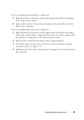
... slack. Installing System Components 87 Align the slots on the replacement fan with the mounting holes in the system chassis. If you are replacing the processor cooling fan: 1 Align the bottom connectors on the replacement fan with the mounting holes in the system chassis. 2 Squeeze the top two release tabs and...
... slack. Installing System Components 87 Align the slots on the replacement fan with the mounting holes in the system chassis. If you are replacing the processor cooling fan: 1 Align the bottom connectors on the replacement fan with the mounting holes in the system chassis. 2 Squeeze the top two release tabs and...

Hardware Owner's Manual (PDF)
Page 88
... Cooling Fan 1 2 3 4 5 1 heat sink fan shroud 3 tab 5 heat sink fan 2 cable slot 4 fan connector cable 5 Replace the heat sink and shroud assembly (see "Removing the Processor" on page 79). 6 Reconnect the fan power cable to replace the battery, see "Troubleshooting the System Battery" on page 47. To determine whether you need...
... Cooling Fan 1 2 3 4 5 1 heat sink fan shroud 3 tab 5 heat sink fan 2 cable slot 4 fan connector cable 5 Replace the heat sink and shroud assembly (see "Removing the Processor" on page 79). 6 Reconnect the fan power cable to replace the battery, see "Troubleshooting the System Battery" on page 47. To determine whether you need...


