Information Update
Page 1
...Optical Drive Support in SUSE Linux SUSE® Linux Enterprise Server 10 Service Pack 1 does not support internal SATA optical drives on systems with the sata_nv driver. The SATA optical drive connected to the kernel line in a future service pack. Add the following text ... Update Memory Module Installation Guidelines The following information updates the memory module installation guidelines. • If only DIMM_1 is installed in your system, its capacity must load the sata_nv driver with the adma mode disabled during and after installation because of an issue with more than ...
...Optical Drive Support in SUSE Linux SUSE® Linux Enterprise Server 10 Service Pack 1 does not support internal SATA optical drives on systems with the sata_nv driver. The SATA optical drive connected to the kernel line in a future service pack. Add the following text ... Update Memory Module Installation Guidelines The following information updates the memory module installation guidelines. • If only DIMM_1 is installed in your system, its capacity must load the sata_nv driver with the adma mode disabled during and after installation because of an issue with more than ...

Information Update
Page 2
System Board Jumpers Expansion Card Update The following updates incorrect expansion card information. System Board Update Figure 6-1 in the Hardware Owner's Manual incorrectly illustrated the system jumpers and the PCI slot (slot 3). Figure 1-1 shows the correct illustration. Figure 1-1. The system board can accommodate up to four expansion cards: • One 3.3-V, half-length 32-bit, 33-MHz PCI (slot 3) • One 2.5-Gb/sec PCIe x1 (slot 4) • Two 2.5-Gb/sec PCIe x8 (slots 1 and 2)
System Board Jumpers Expansion Card Update The following updates incorrect expansion card information. System Board Update Figure 6-1 in the Hardware Owner's Manual incorrectly illustrated the system jumpers and the PCI slot (slot 3). Figure 1-1 shows the correct illustration. Figure 1-1. The system board can accommodate up to four expansion cards: • One 3.3-V, half-length 32-bit, 33-MHz PCI (slot 3) • One 2.5-Gb/sec PCIe x1 (slot 4) • Two 2.5-Gb/sec PCIe x8 (slots 1 and 2)

Information Update
Page 3
...United States and other than its own. disclaims any manner whatsoever without notice. © 2007-2008 Dell Inc. The physical system dimensions have been corrected as follows. Dell Inc. Trademarks used in this document is a registered trademark of supported optical drives. Other trademarks ...names or their products. Reproduction in any proprietary interest in this text: Dell, the DELL logo, and PowerEdge are trademarks of Dell Inc.; is 32 MB instead of 16 MB. System Features Update The following system features are new or updated. • A DVD-RW drive has...
...United States and other than its own. disclaims any manner whatsoever without notice. © 2007-2008 Dell Inc. The physical system dimensions have been corrected as follows. Dell Inc. Trademarks used in this document is a registered trademark of supported optical drives. Other trademarks ...names or their products. Reproduction in any proprietary interest in this text: Dell, the DELL logo, and PowerEdge are trademarks of Dell Inc.; is 32 MB instead of 16 MB. System Features Update The following system features are new or updated. • A DVD-RW drive has...

Getting Started Guide
Page 3
Dell™ PowerEdge™ T105 Systems Getting Started With Your System Model EMT
Dell™ PowerEdge™ T105 Systems Getting Started With Your System Model EMT
Getting Started Guide
Page 5
...DDR II SDRAM memory by installing 512-MB, 1-GB, or 2-GB unbuffered ECC memory modules in the four memory module sockets on the system board; or 800-MHz DDR II SDRAM memory, upgradable to view processor information. It also provides information about other documents you may need ...when setting up your system. single or dual rank. • Support for the following RAID volumes with an optional SAS RAID controller card: simple, spanned, striped (RAID ...
...DDR II SDRAM memory by installing 512-MB, 1-GB, or 2-GB unbuffered ECC memory modules in the four memory module sockets on the system board; or 800-MHz DDR II SDRAM memory, upgradable to view processor information. It also provides information about other documents you may need ...when setting up your system. single or dual rank. • Support for the following RAID volumes with an optional SAS RAID controller card: simple, spanned, striped (RAID ...
Getting Started Guide
Page 6
...Red Hat® Enterprise Linux® (version 5) x86_64 • SUSE® LINUX Enterprise Server 10 x86_64 4 Getting Started With Your System The system board includes the following resolutions: 640 x 480, 800 x 600, 1024 x 768, and 1280 x 1024. • An integrated Gigabit... NIC, capable of graphics memory. Supported Operating Systems Your system supports the following operating systems: • Microsoft® Windows Server® 2003, Standard Edition • Microsoft Windows Server 2003, R2 Standard and Enterprise ...
...Red Hat® Enterprise Linux® (version 5) x86_64 • SUSE® LINUX Enterprise Server 10 x86_64 4 Getting Started With Your System The system board includes the following resolutions: 640 x 480, 800 x 600, 1024 x 768, and 1280 x 1024. • An integrated Gigabit... NIC, capable of graphics memory. Supported Operating Systems Your system supports the following operating systems: • Microsoft® Windows Server® 2003, Standard Edition • Microsoft Windows Server 2003, R2 Standard and Enterprise ...

Getting Started Guide
Page 7
...these options. This document can be offered in all locations. Getting Started With Your System 5 Obtaining Technical Assistance If you purchased separately provides information to the system, software, and/or documentation. Dell Enterprise Training and Certification is available; This service may not be found on the... CDs that came with your system or on support.dell.com and read the updates first because they often supersede information in this document or as expected, see dell.com/training for configuring and managing your Hardware Owner's Manual. ...
...these options. This document can be offered in all locations. Getting Started With Your System 5 Obtaining Technical Assistance If you purchased separately provides information to the system, software, and/or documentation. Dell Enterprise Training and Certification is available; This service may not be found on the... CDs that came with your system or on support.dell.com and read the updates first because they often supersede information in this document or as expected, see dell.com/training for configuring and managing your Hardware Owner's Manual. ...
Getting Started Guide
Page 8
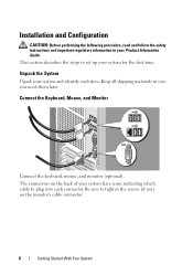
...icons indicating which cable to tighten the screws (if any) on the monitor's cable connector. 6 Getting Started With Your System Unpack the System Upack your system for the first time. The connectors on the back of your Product Information Guide. Be sure to plug into each ...item. This section describes the steps to set up your system and identify each connector. Installation and Configuration CAUTION: Before performing the following procedure, read and follow the safety instructions and important regulatory...
...icons indicating which cable to tighten the screws (if any) on the monitor's cable connector. 6 Getting Started With Your System Unpack the System Upack your system for the first time. The connectors on the back of your Product Information Guide. Be sure to plug into each ...item. This section describes the steps to set up your system and identify each connector. Installation and Configuration CAUTION: Before performing the following procedure, read and follow the safety instructions and important regulatory...

Getting Started Guide
Page 9
Next, plug the other end of the power cable into a grounded electrical outlet or a separate power source such as an uninterrupted power supply (UPS) or a power distribution unit (PDU). The power indicators should light. Adjust the monitor's controls until the displayed image is satisfactory. Getting Started With Your System 7 Connect the System to Power Connect the system's power cable to the system. Turn on the System and Monitor Press the power button on the system and the monitor.
Next, plug the other end of the power cable into a grounded electrical outlet or a separate power source such as an uninterrupted power supply (UPS) or a power distribution unit (PDU). The power indicators should light. Adjust the monitor's controls until the displayed image is satisfactory. Getting Started With Your System 7 Connect the System to Power Connect the system's power cable to the system. Turn on the System and Monitor Press the power button on the system and the monitor.
Getting Started Guide
Page 10
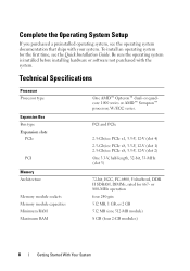
..., PC-6400, Unbuffered, DDR II SDRAM, DIMMs, rated for the first time, see the operating system documentation that ships with the system. Complete the 0perating System Setup If you purchased a preinstalled operating system, see the Quick Installation Guide. or quadcore 1000 series or AMD™ Sempron™ processor, ... Memory module capacities Minimum RAM Maximum RAM One AMD™ Opteron™ dual- Be sure the operating system is installed before installing hardware or software not purchased with your system. or 800-MHz operation four 240-pin 512 MB, 1 GB, or 2 GB 512 MB (one...
..., PC-6400, Unbuffered, DDR II SDRAM, DIMMs, rated for the first time, see the operating system documentation that ships with the system. Complete the 0perating System Setup If you purchased a preinstalled operating system, see the Quick Installation Guide. or quadcore 1000 series or AMD™ Sempron™ processor, ... Memory module capacities Minimum RAM Maximum RAM One AMD™ Opteron™ dual- Be sure the operating system is installed before installing hardware or software not purchased with your system. or 800-MHz operation four 240-pin 512 MB, 1 GB, or 2 GB 512 MB (one...
Getting Started Guide
Page 11
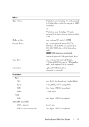
... memory key) Up to two non-hot-plug, 3.5-inch, internal SATA hard drives with a SAS controller card one 4-pin, USB 2.0-compliant Getting Started With Your System 9
... memory key) Up to two non-hot-plug, 3.5-inch, internal SATA hard drives with a SAS controller card one 4-pin, USB 2.0-compliant Getting Started With Your System 9
Getting Started Guide
Page 12
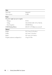
Video Video type Video memory Power AC power supply (per power supply) Wattage Voltage Heat dissipation CMOS Backup Battery Physical Height Width Depth Weight (maximum configuration) Integrated 32 MB 305 W 100-120V/200-240V, 9/4.5A, 50/60 Hz, 1040 BTU/Hour CR 2032 3.0-V lithium ion coin cell 391.55 mm (15.42 inches) 186.9 mm (7.40 inches) 418.5 mm (16.50 inches) 13 kg (28.70 lb) 10 Getting Started With Your System
Video Video type Video memory Power AC power supply (per power supply) Wattage Voltage Heat dissipation CMOS Backup Battery Physical Height Width Depth Weight (maximum configuration) Integrated 32 MB 305 W 100-120V/200-240V, 9/4.5A, 50/60 Hz, 1040 BTU/Hour CR 2032 3.0-V lithium ion coin cell 391.55 mm (15.42 inches) 186.9 mm (7.40 inches) 418.5 mm (16.50 inches) 13 kg (28.70 lb) 10 Getting Started With Your System

Getting Started Guide
Page 13
Environmental NOTE: For additional information about environmental measurements for specific system configurations, see dell.com/environmental_datasheets. Temperature Operating 10° to 35°C (50° to 95°F) Storage -40° to 65°C (-40° to 149°F) ... ips +/- 5% Altitude Operating -15.2 to 3,048 m (-50 to 10,000 ft) Storage -15.2 to 10,600 m (-pion0 to 35,000 ft) Getting Started With Your System 11
Environmental NOTE: For additional information about environmental measurements for specific system configurations, see dell.com/environmental_datasheets. Temperature Operating 10° to 35°C (50° to 95°F) Storage -40° to 65°C (-40° to 149°F) ... ips +/- 5% Altitude Operating -15.2 to 3,048 m (-50 to 10,000 ft) Storage -15.2 to 10,600 m (-pion0 to 35,000 ft) Getting Started With Your System 11

Getting Started Guide
Page 14
12 Getting Started With Your System
12 Getting Started With Your System

Hardware Owner's Manual (PDF)
Page 3
Contents 1 About Your System 11 Other Information You May Need 11 Accessing System Features During Startup 12 Front-Panel Features and Indicators 13 Back-Panel Features and Indicators 15 Connecting External Devices 16 NIC Indicator Codes 16 Power Supply Indicators 17 Diagnostic Lights 18 System Messages 20 Warning Messages 29 Diagnostics Messages 29 Alert Messages 30 2 Using the System Setup Program 31 Entering the System Setup Program 31 Responding to Error Messages 31 Using the System Setup Program 32 Exiting the System Setup Program 33 Contents 3
Contents 1 About Your System 11 Other Information You May Need 11 Accessing System Features During Startup 12 Front-Panel Features and Indicators 13 Back-Panel Features and Indicators 15 Connecting External Devices 16 NIC Indicator Codes 16 Power Supply Indicators 17 Diagnostic Lights 18 System Messages 20 Warning Messages 29 Diagnostics Messages 29 Alert Messages 30 2 Using the System Setup Program 31 Entering the System Setup Program 31 Responding to Error Messages 31 Using the System Setup Program 32 Exiting the System Setup Program 33 Contents 3

Hardware Owner's Manual (PDF)
Page 4
... Screen 36 Integrated Devices Screen 37 System Security Screen 38 Exit Screen 39 System and Setup Password Features 39 Using the System Password 40 Using the Setup Password 42 Disabling a Forgotten Password 43 3 Installing System Components 45 Recommended Tools 45 Inside the System 46 Opening the System 47 Closing the System 47 Front Drive Bezel 48 Removing...
... Screen 36 Integrated Devices Screen 37 System Security Screen 38 Exit Screen 39 System and Setup Password Features 39 Using the System Password 40 Using the Setup Password 42 Disabling a Forgotten Password 43 3 Installing System Components 45 Recommended Tools 45 Inside the System 46 Opening the System 47 Closing the System 47 Front Drive Bezel 48 Removing...
Hardware Owner's Manual (PDF)
Page 5
... Expansion Card 73 Memory 75 Memory Module Upgrade Kits 75 Memory Module Installation Guidelines 75 Addressing Memory With 8-GB Configurations (Microsoft® Windows® Operating System Only 76 Removing a Memory Module 77 Installing a Memory Module 77 Microprocessor 79 Removing the Processor 79 Replacing the Processor 82 Cooling Fans 83 Removing the...
... Expansion Card 73 Memory 75 Memory Module Upgrade Kits 75 Memory Module Installation Guidelines 75 Addressing Memory With 8-GB Configurations (Microsoft® Windows® Operating System Only 76 Removing a Memory Module 77 Installing a Memory Module 77 Microprocessor 79 Removing the Processor 79 Replacing the Processor 82 Cooling Fans 83 Removing the...
Hardware Owner's Manual (PDF)
Page 6
... Parts Procedure 97 Removing the I/O Panel Assembly 97 Replacing the I/O Panel Assembly 98 System Board (Service Only Parts Procedure) . . . . 100 Removing the System Board 100 Installing the System Board 101 4 Troubleshooting Your System 103 Safety First-For You and Your System 103 Start-Up Routine 103 Checking the Equipment 104 Troubleshooting External Connections 104 Troubleshooting...
... Parts Procedure 97 Removing the I/O Panel Assembly 97 Replacing the I/O Panel Assembly 98 System Board (Service Only Parts Procedure) . . . . 100 Removing the System Board 100 Installing the System Board 101 4 Troubleshooting Your System 103 Safety First-For You and Your System 103 Start-Up Routine 103 Checking the Equipment 104 Troubleshooting External Connections 104 Troubleshooting...
Hardware Owner's Manual (PDF)
Page 7
... SCSI Tape Drive . . . . . 119 Troubleshooting a Hard Drive 120 Troubleshooting a SAS or SAS RAID Controller . . . . 122 Troubleshooting Expansion Cards 123 Troubleshooting the Microprocessor 125 5 Running the System Diagnostics 127 Using Dell PowerEdge Diagnostics 127 System Diagnostics Features 127 When to Use the System Diagnostics 128 Running the System Diagnostics 128 System Diagnostics Testing Options 128 Contents 7
... SCSI Tape Drive . . . . . 119 Troubleshooting a Hard Drive 120 Troubleshooting a SAS or SAS RAID Controller . . . . 122 Troubleshooting Expansion Cards 123 Troubleshooting the Microprocessor 125 5 Running the System Diagnostics 127 Using Dell PowerEdge Diagnostics 127 System Diagnostics Features 127 When to Use the System Diagnostics 128 Running the System Diagnostics 128 System Diagnostics Testing Options 128 Contents 7

Hardware Owner's Manual (PDF)
Page 8
... Diagnostics Options 129 Viewing Information and Results 130 6 Jumpers and Connectors 131 System Board Jumpers 131 System Board Connectors 133 Disabling a Forgotten Password 135 7 Getting Help 137 Obtaining ...Assistance 137 Online Services 138 Automated Order-Status Service 139 Support Service 139 Dell Enterprise Training and Certification 139 Problems With Your Order 139 Product Information 139 Returning Items for Warranty Repair or Credit . . . . 140 Before You Call 140 Contacting Dell...
... Diagnostics Options 129 Viewing Information and Results 130 6 Jumpers and Connectors 131 System Board Jumpers 131 System Board Connectors 133 Disabling a Forgotten Password 135 7 Getting Help 137 Obtaining ...Assistance 137 Online Services 138 Automated Order-Status Service 139 Support Service 139 Dell Enterprise Training and Certification 139 Problems With Your Order 139 Product Information 139 Returning Items for Warranty Repair or Credit . . . . 140 Before You Call 140 Contacting Dell...


