
Glossary
Page 1
...agents. bootable media - Certificate authority. cm - Advanced Configuration and Power Interface. blade - BMC - BTU - bus - Celsius. Dell™ Glossary NOTE: For additional information on storage terminology, visit the Storage Networking Industry Association's website at www.snia.org and ... with MIB data from the hard drive. A module that includes power supplies and fans. The modules are mounted into a chassis that contains a processor, memory, and a hard drive. Baseboard management controller. An information pathway between the processor and RAM....
...agents. bootable media - Certificate authority. cm - Advanced Configuration and Power Interface. blade - BMC - BTU - bus - Celsius. Dell™ Glossary NOTE: For additional information on storage terminology, visit the Storage Networking Industry Association's website at www.snia.org and ... with MIB data from the hard drive. A module that includes power supplies and fans. The modules are mounted into a chassis that contains a processor, memory, and a hard drive. Baseboard management controller. An information pathway between the processor and RAM....
Information Update - Intel Xeon 5600 Series Processors
Page 1
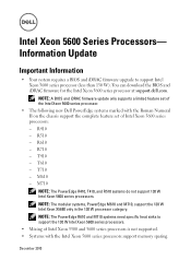
...Numeral II on the chassis support the complete feature set of Intel Xeon 5600 series processors: - T410 - R610 - NOTE: A BIOS and iDRAC firmware update only supports a limited feature set of the Intel Xeon 5600 series processor. • The following new Dell PowerEdge systems marked with ...the Intel Xeon 5600 series processors support memory sparing. You can download the BIOS and iDRAC firmware for the Intel Xeon 5600 series processor at support.dell.com. M610 - Intel Xeon 5600 Series Processors...
...Numeral II on the chassis support the complete feature set of Intel Xeon 5600 series processors: - T410 - R610 - NOTE: A BIOS and iDRAC firmware update only supports a limited feature set of the Intel Xeon 5600 series processor. • The following new Dell PowerEdge systems marked with ...the Intel Xeon 5600 series processors support memory sparing. You can download the BIOS and iDRAC firmware for the Intel Xeon 5600 series processor at support.dell.com. M610 - Intel Xeon 5600 Series Processors...
Hardware Owner's Manual
Page 39
... cycle too many errors. If the problem persists, see "Troubleshooting System Memory" on the LCD. "## & ##" represents the memory module pair implicated by the BIOS. Check chassis cover. LCD overflow message. Review & clear log. W1100 CPU VCORE Regulator temp exceeding range. The system BIOS disabled memory mirroring because it has system for...
... cycle too many errors. If the problem persists, see "Troubleshooting System Memory" on the LCD. "## & ##" represents the memory module pair implicated by the BIOS. Check chassis cover. LCD overflow message. Review & clear log. W1100 CPU VCORE Regulator temp exceeding range. The system BIOS disabled memory mirroring because it has system for...
Hardware Owner's Manual
Page 87
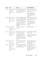
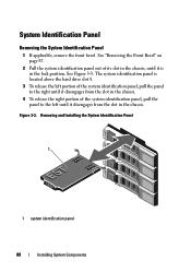
... 3-2. Removing and Installing the Front Bezel 3 2 1 1 release latch 3 front bezel 2 key lock Installing the Front Bezel 1 Hook the right end of the bezel onto the chassis. 2 Fit the free end of the bezel and pull the bezel away from the front panel. 4 Unhook the right end of the bezel onto the...
... 3-2. Removing and Installing the Front Bezel 3 2 1 1 release latch 3 front bezel 2 key lock Installing the Front Bezel 1 Hook the right end of the bezel onto the chassis. 2 Fit the free end of the bezel and pull the bezel away from the front panel. 4 Unhook the right end of the bezel onto the...
Hardware Owner's Manual
Page 88
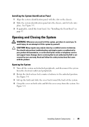
... Installing System Components See Figure 3-3. See "Removing the Front Bezel" on page 87. 2 Pull the system identification panel out of its slot in the chassis, until it is located above the hard drive slot 8. 3 To release the left portion of the system identification panel, pull the panel to the right... until it disengages from the slot in the chassis. 4 To release the right portion of the system identification panel, pull the panel to the left until it disengages from the slot in the lock...
... Installing System Components See Figure 3-3. See "Removing the Front Bezel" on page 87. 2 Pull the system identification panel out of its slot in the chassis, until it is located above the hard drive slot 8. 3 To release the left portion of the system identification panel, pull the panel to the right... until it disengages from the slot in the chassis. 4 To release the right portion of the system identification panel, pull the panel to the left until it disengages from the slot in the lock...
Hardware Owner's Manual
Page 89
Read and follow the safety instructions that is not authorized by Dell is not covered by your product documentation, or as authorized in your warranty. To avoid injury, do not attempt to the unlocked position. See Figure 3-4. ... team. Damage due to assist you need to lift the system, get others to servicing that came with the slot on the chassis. 2 Slide the system identification panel into the chassis, until it locks into place. See Figure 3-4. 3 Lift up the latch and slide the cover back toward the back of the...
Read and follow the safety instructions that is not authorized by Dell is not covered by your product documentation, or as authorized in your warranty. To avoid injury, do not attempt to the unlocked position. See Figure 3-4. ... team. Damage due to assist you need to lift the system, get others to servicing that came with the slot on the chassis. 2 Slide the system identification panel into the chassis, until it locks into place. See Figure 3-4. 3 Lift up the latch and slide the cover back toward the back of the...
Hardware Owner's Manual
Page 90
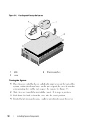
See Figure 3-4. 2 Slide the cover toward the front of the chassis till it slightly toward the back of the system, so that the chassis hooks on the back edge of the cover fit over the corresponding slots on the back edge of the chassis. Figure 3-4. Opening and Closing the System 1 2 3 1 latch 3 cover 2 latch release lock Closing the System 1 Place the cover onto the chassis and offset it snaps in position. 3 Push down the latch to lever the cover into the closed position. 4 Rotate the latch release lock in a clockwise direction to secure the cover. 90 Installing System Components
See Figure 3-4. 2 Slide the cover toward the front of the chassis till it slightly toward the back of the system, so that the chassis hooks on the back edge of the cover fit over the corresponding slots on the back edge of the chassis. Figure 3-4. Opening and Closing the System 1 2 3 1 latch 3 cover 2 latch release lock Closing the System 1 Place the cover onto the chassis and offset it snaps in position. 3 Push down the latch to lever the cover into the closed position. 4 Rotate the latch release lock in a clockwise direction to secure the cover. 90 Installing System Components

Hardware Owner's Manual
Page 107
See "Installing a Memory Riser" on the chassis. 2 Lower the memory-riser guide into the system until the tabs click into place. 3 Install the memory risers. Hard Drives All drives connect to format. ...
See "Installing a Memory Riser" on the chassis. 2 Lower the memory-riser guide into the system until the tabs click into place. 3 Install the memory risers. Hard Drives All drives connect to format. ...

Hardware Owner's Manual
Page 111
Figure 3-13. To remove the chassis blank, press down and push the blue release tab toward the front of the drive carrier and open the handle. 4 Insert the hard-drive carrier into the drive bay until the carrier contacts the backplane. 5 Close the handle to a 16-hard-drive configuration, turn off the system and remove all the chassis blanks. Removing a Chassis Blank 2 1 1 chassis blank 2 release tab Installing System Components 111 See Figure 3-13. 3 Press the button on the front of the system. NOTE: If you are upgrading your system to lock the drive in place.
Figure 3-13. To remove the chassis blank, press down and push the blue release tab toward the front of the drive carrier and open the handle. 4 Insert the hard-drive carrier into the drive bay until the carrier contacts the backplane. 5 Close the handle to a 16-hard-drive configuration, turn off the system and remove all the chassis blanks. Removing a Chassis Blank 2 1 1 chassis blank 2 release tab Installing System Components 111 See Figure 3-13. 3 Press the button on the front of the system. NOTE: If you are upgrading your system to lock the drive in place.
Hardware Owner's Manual
Page 129
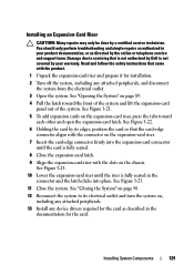
..., and disconnect the system from the electrical outlet. 3 Open the system. Read and follow the safety instructions that is not authorized by Dell is not covered by your product documentation, or as described in the documentation for the card as directed by the online or telephone service ...Pull the latch toward each other and open the expansion-card latch. See Figure 3-23. 11 Close the system. See "Opening the System" on the chassis. See Figure 3-23. 10 Lower the expansion-card riser until the riser is fully seated. 8 Close the expansion-card latch. 9 Align the expansion-card...
..., and disconnect the system from the electrical outlet. 3 Open the system. Read and follow the safety instructions that is not authorized by Dell is not covered by your product documentation, or as described in the documentation for the card as directed by the online or telephone service ...Pull the latch toward each other and open the expansion-card latch. See Figure 3-23. 11 Close the system. See "Opening the System" on the chassis. See Figure 3-23. 10 Lower the expansion-card riser until the riser is fully seated. 8 Close the expansion-card latch. 9 Align the expansion-card...
Hardware Owner's Manual
Page 145
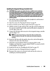
... by a certified service technician. Installing the Integrated Storage Controller Card CAUTION: Many repairs may only be done by Dell is fully seated and the plastic card guides fit over the edges of the chassis. 7 Attach the connector labeled "SAS A" to connector SAS A on the backplane, and attach the connector labeled "SAS B" to...
... by a certified service technician. Installing the Integrated Storage Controller Card CAUTION: Many repairs may only be done by Dell is fully seated and the plastic card guides fit over the edges of the chassis. 7 Attach the connector labeled "SAS A" to connector SAS A on the backplane, and attach the connector labeled "SAS B" to...
Hardware Owner's Manual
Page 147
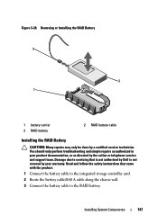
... product. 1 Connect the battery cable to the integrated storage controller card. 2 Route the battery cable/SAS A cable along the chassis wall. 3 Connect the battery cable to servicing that is not authorized by Dell is not covered by your product documentation, or as directed by a certified service technician. Damage due to the RAID...
... product. 1 Connect the battery cable to the integrated storage controller card. 2 Route the battery cable/SAS A cable along the chassis wall. 3 Connect the battery cable to servicing that is not authorized by Dell is not covered by your product documentation, or as directed by a certified service technician. Damage due to the RAID...
Hardware Owner's Manual
Page 148
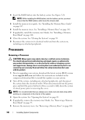
... a Memory- Processors Removing a Processor CAUTION: Many repairs may only be done by a certified service technician. When disconnected from support.dell.com and follow the instructions included in the compressed download file to removing the cover. NOTE: While installing the RAID battery into the...page 101. 7 If applicable, install the memory-riser blanks. Read and follow the safety instructions that the RAID battery cable faces the chassis wall. 5 Install the memory-riser guide. Riser Blank" on page 100. 148 Installing System Components See "Removing a Memory Riser" on...
... a Memory- Processors Removing a Processor CAUTION: Many repairs may only be done by a certified service technician. When disconnected from support.dell.com and follow the instructions included in the compressed download file to removing the cover. NOTE: While installing the RAID battery into the...page 101. 7 If applicable, install the memory-riser blanks. Read and follow the safety instructions that the RAID battery cable faces the chassis wall. 5 Install the memory-riser guide. Riser Blank" on page 100. 148 Installing System Components See "Removing a Memory Riser" on...
Hardware Owner's Manual
Page 155
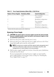
... the Power Supply Blank" on . 1 Disconnect the power cable from the power source. 2 Disconnect the power cable from the power distribution board and clear the chassis. Table 3-5. NOTE: You may have to release it interferes with a limited load. If you are permanently removing the power supply, you must install a power supply...
... the Power Supply Blank" on . 1 Disconnect the power cable from the power source. 2 Disconnect the power cable from the power distribution board and clear the chassis. Table 3-5. NOTE: You may have to release it interferes with a limited load. If you are permanently removing the power supply, you must install a power supply...

Hardware Owner's Manual
Page 156
... cable into place. NOTE: If you unlatched the cable management arm in watts) is listed on page 157. 3 Slide the new power supply into the chassis until the power supply is fully seated and the release latch snaps into a power outlet. 156 Installing System Components See "Removing the Power Supply Blank...
... cable into place. NOTE: If you unlatched the cable management arm in watts) is listed on page 157. 3 Slide the new power supply into the chassis until the power supply is fully seated and the release latch snaps into a power outlet. 156 Installing System Components See "Removing the Power Supply Blank...

Hardware Owner's Manual
Page 157
... cooling, the power supply blank must be done by pulling outward on page 89. Damage due to signify that is not authorized by Dell is not covered by the manufacturer. CAUTION: Many repairs may only be installed in a system, allow several seconds for additional information.... the Velcro strap. System Battery Replacing the System Battery WARNING: There is a danger of a new battery exploding if it clicks into the chassis until it is functioning properly. See "Opening the System" on the blank. Installing System Components 157 CAUTION: When connecting the power cable,...
... cooling, the power supply blank must be done by pulling outward on page 89. Damage due to signify that is not authorized by Dell is not covered by the manufacturer. CAUTION: Many repairs may only be installed in a system, allow several seconds for additional information.... the Velcro strap. System Battery Replacing the System Battery WARNING: There is a danger of a new battery exploding if it clicks into the chassis until it is functioning properly. See "Opening the System" on the blank. Installing System Components 157 CAUTION: When connecting the power cable,...
Hardware Owner's Manual
Page 160
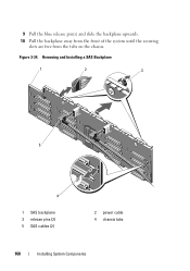
Removing and Installing a SAS Backplane 1 2 3 5 4 1 SAS backplane 3 release pins (2) 5 SAS cables (2) 2 power cable 4 chassis tabs 160 Installing System Components 9 Pull the blue release pin(s) and slide the backplane upwards. 10 Pull the backplane away from the front of the system until the securing slots are free from the tabs on the chassis. Figure 3-34.
Removing and Installing a SAS Backplane 1 2 3 5 4 1 SAS backplane 3 release pins (2) 5 SAS cables (2) 2 power cable 4 chassis tabs 160 Installing System Components 9 Pull the blue release pin(s) and slide the backplane upwards. 10 Pull the backplane away from the front of the system until the securing slots are free from the tabs on the chassis. Figure 3-34.
Hardware Owner's Manual
Page 161
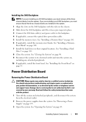
...- Installing System Components 161 See "Closing the System" on page 90. 9 Reconnect the system to servicing that is not authorized by Dell is not covered by your product documentation, or as directed by a certified service technician. Power Distribution Board Removing the Power Distribution Board ...as authorized in their original locations. See "Installing the Front Bezel" on page 89. Read and follow the safety instructions that all the three chassis blanks from the system. See "Installing a Memory Riser" on page 155. 3 Open the system. See "Removing a Power Supply" on ...
...- Installing System Components 161 See "Closing the System" on page 90. 9 Reconnect the system to servicing that is not authorized by Dell is not covered by your product documentation, or as directed by a certified service technician. Power Distribution Board Removing the Power Distribution Board ...as authorized in their original locations. See "Installing the Front Bezel" on page 89. Read and follow the safety instructions that all the three chassis blanks from the system. See "Installing a Memory Riser" on page 155. 3 Open the system. See "Removing a Power Supply" on ...
Hardware Owner's Manual
Page 162
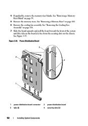
... until the tabs on the board are free from the securing slots on page 99. 5 Remove the memory risers. See "Removing a MemoryRiser Blank" on the chassis. See "Removing a Memory Riser" on page 100. 6 Remove the cooling fan assembly. Power Distribution Board 3 2 4 1 1 power distribution board connector 3 tabs (2) 2 power distribution board 4 securing slots...
... until the tabs on the board are free from the securing slots on page 99. 5 Remove the memory risers. See "Removing a MemoryRiser Blank" on the chassis. See "Removing a Memory Riser" on page 100. 6 Remove the cooling fan assembly. Power Distribution Board 3 2 4 1 1 power distribution board connector 3 tabs (2) 2 power distribution board 4 securing slots...
Hardware Owner's Manual
Page 163
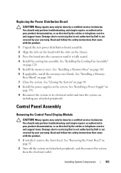
... on the board with the product. 1 If installed, remove the front bezel. Read and follow the safety instructions that is not authorized by Dell is not covered by the online or telephone service and support team. See "Installing a Memory- You should only perform troubleshooting and simple repairs... cooling fan assembly. Riser Blank" on page 100. 7 Close the system. Damage due to its electrical outlet and turn the system on the chassis. 3 Press the board into the connector until it is not covered by the online or telephone service and support team. You should only perform ...
... on the board with the product. 1 If installed, remove the front bezel. Read and follow the safety instructions that is not authorized by Dell is not covered by the online or telephone service and support team. See "Installing a Memory- You should only perform troubleshooting and simple repairs... cooling fan assembly. Riser Blank" on page 100. 7 Close the system. Damage due to its electrical outlet and turn the system on the chassis. 3 Press the board into the connector until it is not covered by the online or telephone service and support team. You should only perform ...


