Information Update
Page 1
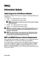
... system. Loading the latest BIOS version from support.dell.com will only recognize and display 63.75 GB during POST. • 128 GB - 16 x 8-GB quad-rank memory modules • 256 GB - 32 x 8-GB quad-rank memory modules NOTE: Prior to ensure full functionality and compatibility... must update the firmware for 8-GB Memory Modules Your Dell™ PowerEdge™ R900 system now supports the following 8-GB memory configurations: • 32 GB - 4 x 8-GB quad-rank memory modules • 64 GB - 8 x 8-GB quad-rank memory modules NOTE: If 64 GB of memory is installed, the system will ensure ...
... system. Loading the latest BIOS version from support.dell.com will only recognize and display 63.75 GB during POST. • 128 GB - 16 x 8-GB quad-rank memory modules • 256 GB - 32 x 8-GB quad-rank memory modules NOTE: Prior to ensure full functionality and compatibility... must update the firmware for 8-GB Memory Modules Your Dell™ PowerEdge™ R900 system now supports the following 8-GB memory configurations: • 32 GB - 4 x 8-GB quad-rank memory modules • 64 GB - 8 x 8-GB quad-rank memory modules NOTE: If 64 GB of memory is installed, the system will ensure ...

Information Update
Page 3
...with the chipset, but is unable to operate normally. Applicable only for BIOS 1.1.9 and BMC 2.27 and later. See "Troubleshooting System Memory" in your Hardware Owner's Manual. Information only. E1914 DRAC5 Conn 2 Cbl DRAC5 cable is a problem Hardware Owner's Manual. E2122 Fatal Mem ...Reset System memory failed. New SEL Sensor Messages The following SEL sensor messages have been added to the systems management software and remote access card software...
...with the chipset, but is unable to operate normally. Applicable only for BIOS 1.1.9 and BMC 2.27 and later. See "Troubleshooting System Memory" in your Hardware Owner's Manual. Information only. E1914 DRAC5 Conn 2 Cbl DRAC5 cable is a problem Hardware Owner's Manual. E2122 Fatal Mem ...Reset System memory failed. New SEL Sensor Messages The following SEL sensor messages have been added to the systems management software and remote access card software...
Getting Started Guide
Page 5
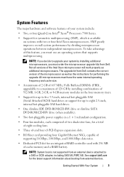
... Support for an integrated RAID controller card with two or four Intel Xeon microprocessors. The upgrade kit from Dell. NOTE: System boot is available on systems with 256 MB of cache memory and a RAID battery. SMP greatly improves overall system performance by installing combinations of 512-MB, 1-GB,... 2-GB, or 4-GB memory modules in the four memory risers. • Support for up to five 3.5-inch, internal hot-pluggable SAS (Serial Attached SCSI) hard drives or support ...
... Support for an integrated RAID controller card with two or four Intel Xeon microprocessors. The upgrade kit from Dell. NOTE: System boot is available on systems with 256 MB of cache memory and a RAID battery. SMP greatly improves overall system performance by installing combinations of 512-MB, 1-GB,... 2-GB, or 4-GB memory modules in the four memory risers. • Support for up to five 3.5-inch, internal hot-pluggable SAS (Serial Attached SCSI) hard drives or support ...

Getting Started Guide
Page 6
... with support for system ID and error messaging. For more information about specific features, see "Technical Specifications" on the back) capable of graphics memory with 65,536 colors; This video subsystem contains a minimum of 16MB of external support for a diskette drive, a CD-ROM drive, a ...keyboard, a mouse, or a USB flash drive. • Optional remote access controller (Dell Remote Assistant Card or RAC) for remote systems management. • An integrated VGA-compatible video subsystem with SP2 • Red Hat® Enterprise Linux4...
... with support for system ID and error messaging. For more information about specific features, see "Technical Specifications" on the back) capable of graphics memory with 65,536 colors; This video subsystem contains a minimum of 16MB of external support for a diskette drive, a CD-ROM drive, a ...keyboard, a mouse, or a USB flash drive. • Optional remote access controller (Dell Remote Assistant Card or RAC) for remote systems management. • An integrated VGA-compatible video subsystem with SP2 • Red Hat® Enterprise Linux4...
Getting Started Guide
Page 13
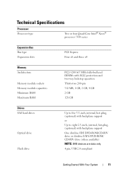
... four Quad-Core Intel® Xeon® processor 7300 series Expansion Bus Bus type Expansion slots PCI Express Four x8 and three x4 Memory Architecture Memory module sockets Memory module capacities Minimum RAM Maximum RAM PC2-5200 667 MHz fully-buffered DIMMs with ECC protection and two-way lockstep operation Thirty-two 240...
... four Quad-Core Intel® Xeon® processor 7300 series Expansion Bus Bus type Expansion slots PCI Express Four x8 and three x4 Memory Architecture Memory module sockets Memory module capacities Minimum RAM Maximum RAM PC2-5200 667 MHz fully-buffered DIMMs with ECC protection and two-way lockstep operation Thirty-two 240...

Getting Started Guide
Page 14
... integrated 1-GB NICs) 9-pin, DTE, 16550-compatible Two 4 pin, USB 2.0 compliant 15-pin VGA 15-pin VGA Two 4 pin, USB 2.0 compliant Video Video type Video memory ATI ES1000 video controller; VGA connector 16 MB of DDR SDRAM Power AC power supply (per power supply) Wattage (output) Voltage (input) Maximum power dissipation...
... integrated 1-GB NICs) 9-pin, DTE, 16550-compatible Two 4 pin, USB 2.0 compliant 15-pin VGA 15-pin VGA Two 4 pin, USB 2.0 compliant Video Video type Video memory ATI ES1000 video controller; VGA connector 16 MB of DDR SDRAM Power AC power supply (per power supply) Wattage (output) Voltage (input) Maximum power dissipation...
Hardware Owner's Manual (PDF)
Page 4
Responding to Error Messages 41 Using the System Setup Program 42 System Setup Options 43 Main Screen 43 Memory Information Screen 45 CPU Information Screen 45 Integrated Devices Screen 46 PCI IRQ Screen 47 Serial Communication Screen 47 Embedded Server Management Screen 48 System ...
Responding to Error Messages 41 Using the System Setup Program 42 System Setup Options 43 Main Screen 43 Memory Information Screen 45 CPU Information Screen 45 Integrated Devices Screen 46 PCI IRQ Screen 47 Serial Communication Screen 47 Embedded Server Management Screen 48 System ...

Hardware Owner's Manual (PDF)
Page 6
... Into an Optical Drive Mounting Tray 92 System Memory 92 General Memory Module Installation Guidelines . 92 Non-Optimal Memory Configurations 93 Memory Sparing Support 93 Memory Mirroring Support 94 Removing a Memory Riser 96 Installing a Memory Riser 98 Memory Population Rules 98 Removing the Memory Riser Cover 99 Installing Memory Modules 99 Removing Memory Modules 101 Processors 101 Removing a Processor Heat Sink...
... Into an Optical Drive Mounting Tray 92 System Memory 92 General Memory Module Installation Guidelines . 92 Non-Optimal Memory Configurations 93 Memory Sparing Support 93 Memory Mirroring Support 94 Removing a Memory Riser 96 Installing a Memory Riser 98 Memory Population Rules 98 Removing the Memory Riser Cover 99 Installing Memory Modules 99 Removing Memory Modules 101 Processors 101 Removing a Processor Heat Sink...
Hardware Owner's Manual (PDF)
Page 8
... a Wet System 134 Troubleshooting a Damaged System 135 Troubleshooting the System Battery 136 Troubleshooting Power Supplies 137 Troubleshooting System Cooling 138 Troubleshooting a Fan 138 Troubleshooting System Memory 139 Troubleshooting an Optical Drive 141 Troubleshooting a Hard Drive 142 Troubleshooting a SAS or SAS RAID Controller Card . 144 Troubleshooting Expansion Cards 145 Troubleshooting Processors 147...
... a Wet System 134 Troubleshooting a Damaged System 135 Troubleshooting the System Battery 136 Troubleshooting Power Supplies 137 Troubleshooting System Cooling 138 Troubleshooting a Fan 138 Troubleshooting System Memory 139 Troubleshooting an Optical Drive 141 Troubleshooting a Hard Drive 142 Troubleshooting a SAS or SAS RAID Controller Card . 144 Troubleshooting Expansion Cards 145 Troubleshooting Processors 147...

Hardware Owner's Manual (PDF)
Page 23
... by the user information only. on. • The power is for at least five seconds until an error code appears on page 165. E1116 Temp Memory Memory has exceeded acceptable temperature and has been disabled to prevent damage to boot, press the System ID button for can change the system ID and...
... by the user information only. on. • The power is for at least five seconds until an error code appears on page 165. E1116 Temp Memory Memory has exceeded acceptable temperature and has been disabled to prevent damage to boot, press the System ID button for can change the system ID and...

Hardware Owner's Manual (PDF)
Page 29
...has been removed from the system. Reseat the cable. Reseat the cable. E2010 No Memory No memory is missing or bad. See "General Memory Module Installation Guidelines" on page 139. See "Troubleshooting System Memory" on page 92. page 139. If the problem persists, see your RAID documentation.... E1A14 SAS Cable A SAS cable A is installed in the system. Memory System Memory" on setup and use of BMC. About Your System 29 E2012 Unusable Memory Memory is missing or bad. See the BMC User's Guide for more information on subsystem failure....
...has been removed from the system. Reseat the cable. Reseat the cable. E2010 No Memory No memory is missing or bad. See "General Memory Module Installation Guidelines" on page 139. See "Troubleshooting System Memory" on page 92. page 139. If the problem persists, see your RAID documentation.... E1A14 SAS Cable A SAS cable A is installed in the system. Memory System Memory" on setup and use of BMC. About Your System 29 E2012 Unusable Memory Memory is missing or bad. See the BMC User's Guide for more information on subsystem failure....

Hardware Owner's Manual (PDF)
Page 30
... on page 165. Programmable interval timer error. See "Getting Help" on page 165. SIO failure. See "Getting Help" on page 165. See "Troubleshooting System Memory" on page 165. Timer refresh failure. Parity error. BIOS shutdown test failure. See "Getting Help" on page 139. See "Getting Help" on page 165....If problem persists, see "Getting Help" on page 165. See "Getting Help" on page 165. See "Getting Help" on page 165. BIOS POST memory test failure. Table 1-5. CMOS RAM not functioning properly. DMA controller failure. Keyboard controller failure.
... on page 165. Programmable interval timer error. See "Getting Help" on page 165. SIO failure. See "Getting Help" on page 165. See "Troubleshooting System Memory" on page 165. Timer refresh failure. Parity error. BIOS shutdown test failure. See "Getting Help" on page 139. See "Getting Help" on page 165....If problem persists, see "Getting Help" on page 165. See "Getting Help" on page 165. See "Getting Help" on page 165. BIOS POST memory test failure. Table 1-5. CMOS RAM not functioning properly. DMA controller failure. Keyboard controller failure.

Hardware Owner's Manual (PDF)
Page 31
.... About Your System 31 LCD Status Messages Code Test Causes Corrective Actions E201F DRAC Config Dell Remote Assistant Card (DRAC) configuration failure. E2020 CPU Config processor configuration failure. Check screen for specific error messages. E2021 Memory Population Incorrect memory Check screen for specific error messages. Ensure that DRAC cables and connectors are properly...
.... About Your System 31 LCD Status Messages Code Test Causes Corrective Actions E201F DRAC Config Dell Remote Assistant Card (DRAC) configuration failure. E2020 CPU Config processor configuration failure. Check screen for specific error messages. E2021 Memory Population Incorrect memory Check screen for specific error messages. Ensure that DRAC cables and connectors are properly...

Hardware Owner's Manual (PDF)
Page 32
...Actions The system BIOS has See "Troubleshooting spared the memory System Memory" on page 139. The system BIOS has See "Troubleshooting disabled memory mirroring System Memory" on the Southbound side has failed. One of the message. If no memory card is present, the "Crd #" string is ... the DIMM pair implicated by the BIOS. System cover has been removed. If no memory card is present, the "Crd #" string is left out of the connections in the Fully Buffered DIMM (FBDIMM) memory subsystem link on page 139. One of the message. Information only. 32 About Your...
...Actions The system BIOS has See "Troubleshooting spared the memory System Memory" on page 139. The system BIOS has See "Troubleshooting disabled memory mirroring System Memory" on the Southbound side has failed. One of the message. If no memory card is present, the "Crd #" string is ... the DIMM pair implicated by the BIOS. System cover has been removed. If no memory card is present, the "Crd #" string is left out of the connections in the Fully Buffered DIMM (FBDIMM) memory subsystem link on page 139. One of the message. Information only. 32 About Your...
Hardware Owner's Manual (PDF)
Page 34
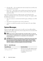
...message will reappear under the following conditions: • The sensor returns to remove the system cover and access any memory error which causes memory loss happens during memory configuration. 34 About Your System Any of each message. Table 1-6. CAUTION: Only trained service technicians are detected....off the system and disconnect it from another source that maps to the normal state. System Messages System Message Error: Incorrect memory configuration. You can occur and a brief description of these actions will lose the event history for the application that can ...
...message will reappear under the following conditions: • The sensor returns to remove the system cover and access any memory error which causes memory loss happens during memory configuration. 34 About Your System Any of each message. Table 1-6. CAUTION: Only trained service technicians are detected....off the system and disconnect it from another source that maps to the normal state. System Messages System Message Error: Incorrect memory configuration. You can occur and a brief description of these actions will lose the event history for the application that can ...

Hardware Owner's Manual (PDF)
Page 35
... subsystem reset failed Faulty diskette/tape drive controller Drive not ready Diskette missing from or improperly inserted in CMOS, but the memory configuration is not recommended by Dell. Redundant memory disabled! Redundant memory was set to enabled in diskette drive About Your System 35 NVRAM_CLR jumper is NVRAM_CLR jumper is no any key to...
... subsystem reset failed Faulty diskette/tape drive controller Drive not ready Diskette missing from or improperly inserted in CMOS, but the memory configuration is not recommended by Dell. Redundant memory disabled! Redundant memory was set to enabled in diskette drive About Your System 35 NVRAM_CLR jumper is NVRAM_CLR jumper is no any key to...

Hardware Owner's Manual (PDF)
Page 37
... or improperly seated DIMMs or defective system board Memory double word logic failure at address, read value expecting value Memory odd/even logic failure at address, read value expecting value Memory write/read failure at address, read value expecting value Memory tests terminated by keystroke POST memory test terminated by pressing the No boot device...
... or improperly seated DIMMs or defective system board Memory double word logic failure at address, read value expecting value Memory odd/even logic failure at address, read value expecting value Memory write/read failure at address, read value expecting value Memory tests terminated by keystroke POST memory test terminated by pressing the No boot device...

Hardware Owner's Manual (PDF)
Page 38
... operation failed Faulty diskette or hard-disk drive Shutdown failure Defective system board Spare bank enabled DIMM sparing has been enabled The amount of system memory DIMMs have been added or removed has changed Time-of-day clock stopped Defective battery or faulty chip Time-of-day not set - Utility partition...
... operation failed Faulty diskette or hard-disk drive Shutdown failure Defective system board Spare bank enabled DIMM sparing has been enabled The amount of system memory DIMMs have been added or removed has changed Time-of-day clock stopped Defective battery or faulty chip Time-of-day not set - Utility partition...

Hardware Owner's Manual (PDF)
Page 42
... used to exit the program. When is pressed in a submenu, the parent menu is asked whether changes should be saved or discarded. NOTE: After installing a memory upgrade, it performs the same function. 42 Using the System Setup Program
... used to exit the program. When is pressed in a submenu, the parent menu is asked whether changes should be saved or discarded. NOTE: After installing a memory upgrade, it performs the same function. 42 Using the System Setup Program

Hardware Owner's Manual (PDF)
Page 44
...assignments. See "Serial Communication Screen" on page 46. Table 2-2. System Setup Program Options Option System Time System Date Memory Information CPU Information Boot Sequence USB Flash Drive Emulation Type Boot Sequence Retry Integrated Devices PCI IRQ Assigment Serial Communication Embedded... system time Set up the system date Set up Serial Communication parameters. See "Integrated Devices Screen" on page 47. Set up the memory configuration. See "System Security Screen" on page 48. NOTE: The System Setup program defaults are listed under their respective options, where ...
...assignments. See "Serial Communication Screen" on page 46. Table 2-2. System Setup Program Options Option System Time System Date Memory Information CPU Information Boot Sequence USB Flash Drive Emulation Type Boot Sequence Retry Integrated Devices PCI IRQ Assigment Serial Communication Embedded... system time Set up the system date Set up Serial Communication parameters. See "Integrated Devices Screen" on page 47. Set up the memory configuration. See "System Security Screen" on page 48. NOTE: The System Setup program defaults are listed under their respective options, where ...


