
User Manual
Page 5
Turning On The System Figure 5. Securing The Power Cable(s) Figure 4. Turning on the System 5 Connect the system's power cable(s) to the system and, if a monitor is used, connect the monitor's power cable to the cable strap. Plug the other end of the power cable(s) into a grounded electrical outlet or a separate power source such as shown in the illustration, and attach to the monitor. Securing Power Cable(s) Bend the system power cable(s), as an uninterruptible power supply (UPS) or a power distribution unit (PDU).
Turning On The System Figure 5. Securing The Power Cable(s) Figure 4. Turning on the System 5 Connect the system's power cable(s) to the system and, if a monitor is used, connect the monitor's power cable to the cable strap. Plug the other end of the power cable(s) into a grounded electrical outlet or a separate power source such as shown in the illustration, and attach to the monitor. Securing Power Cable(s) Bend the system power cable(s), as an uninterruptible power supply (UPS) or a power distribution unit (PDU).

User Manual
Page 7
...for updates on the device described in this document in other documents. Obtaining Technical Assistance If you purchased with 1100 W DC power supply unit) 7 de C.V. Dell offers comprehensive hardware training and certification. Paseo de la Reforma 2620 -11º Piso Col. de México, S.A. ... system updates, and system components that you do not understand a procedure in all locations. Model number: Supply voltage: E16S 100-240 V CA (with 495 W, 750 W, and 1100 W AC Power Supply Unit) or -(48-60) V de CC (with your system, including those pertaining to troubleshoot the ...
...for updates on the device described in this document in other documents. Obtaining Technical Assistance If you purchased with 1100 W DC power supply unit) 7 de C.V. Dell offers comprehensive hardware training and certification. Paseo de la Reforma 2620 -11º Piso Col. de México, S.A. ... system updates, and system components that you do not understand a procedure in all locations. Model number: Supply voltage: E16S 100-240 V CA (with 495 W, 750 W, and 1100 W AC Power Supply Unit) or -(48-60) V de CC (with your system, including those pertaining to troubleshoot the ...

User Manual
Page 8
... (AC power supply unit) 12 A - 6.5 A (X 2) (with 1100 W AC power supply unit) 10 A - 5 A (X 2) (with 750 W AC power supply unit) 6.5 A - 3 A (X 2) (with 495 W AC power supply unit) 32 A (X 2) (with 1100 W DC power supply unit) Technical Specifications NOTE: The following specifications are only those required by law to support.dell.com. For a complete and current listing of the specifications for your system. DC Power Supply (per power supply) Wattage...
... (AC power supply unit) 12 A - 6.5 A (X 2) (with 1100 W AC power supply unit) 10 A - 5 A (X 2) (with 750 W AC power supply unit) 6.5 A - 3 A (X 2) (with 495 W AC power supply unit) 32 A (X 2) (with 1100 W DC power supply unit) Technical Specifications NOTE: The following specifications are only those required by law to support.dell.com. For a complete and current listing of the specifications for your system. DC Power Supply (per power supply) Wattage...

Owner's Manual
Page 5
... Card...66 Processors...66 Removing A Processor...67 Installing A Processor...70 Power Supplies...71 Hot Spare Feature...72 Removing An AC Power Supply...72 Installing An AC Power Supply...73 Wiring Instructions For A DC Power Supply...74 Removing A DC Power Supply...76 Installing A DC Power Supply...77 Removing The Power Supply Blank...78 Installing The Power Supply Blank...78 System Battery...78 Replacing The System Battery...78...
... Card...66 Processors...66 Removing A Processor...67 Installing A Processor...70 Power Supplies...71 Hot Spare Feature...72 Removing An AC Power Supply...72 Installing An AC Power Supply...73 Wiring Instructions For A DC Power Supply...74 Removing A DC Power Supply...76 Installing A DC Power Supply...77 Removing The Power Supply Blank...78 Installing The Power Supply Blank...78 System Battery...78 Replacing The System Battery...78...

Owner's Manual
Page 6
... NIC...98 Troubleshooting A Wet System...98 Troubleshooting A Damaged System...99 Troubleshooting The System Battery...100 Troubleshooting Power Supplies...100 Troubleshooting Cooling Problems...100 Troubleshooting Cooling Fans...101 Troubleshooting System Memory...101 Troubleshooting An Internal USB Key...102... A Storage Controller...104 Troubleshooting Expansion Cards...105 Troubleshooting Processors...106 5 Using System Diagnostics...107 Dell Online Diagnostics...107 Dell Embedded System Diagnostics...107 When To Use The Embedded System Diagnostics 107 Running The Embedded System ...
... NIC...98 Troubleshooting A Wet System...98 Troubleshooting A Damaged System...99 Troubleshooting The System Battery...100 Troubleshooting Power Supplies...100 Troubleshooting Cooling Problems...100 Troubleshooting Cooling Fans...101 Troubleshooting System Memory...101 Troubleshooting An Internal USB Key...102... A Storage Controller...104 Troubleshooting Expansion Cards...105 Troubleshooting Processors...106 5 Using System Diagnostics...107 Dell Online Diagnostics...107 Dell Embedded System Diagnostics...107 When To Use The Embedded System Diagnostics 107 Running The Embedded System ...

Owner's Manual
Page 9
... and device driver errors when running certain operating systems. This button can be pressed using the power button causes the system to perform a graceful shutdown before power to the system is pressed, the LCD panel on the front and the system status indicator ...Panel Features and Indicators-8 Hard Drive System Item Indicator, Button, or Icon Description Connector 1 Power-on indicator, power button The power-on . The ports are USB 2.0-compliant. The power button controls the power supply output to the system. If the system stops responding during POST, press and hold the...
... and device driver errors when running certain operating systems. This button can be pressed using the power button causes the system to perform a graceful shutdown before power to the system is pressed, the LCD panel on the front and the system status indicator ...Panel Features and Indicators-8 Hard Drive System Item Indicator, Button, or Icon Description Connector 1 Power-on indicator, power button The power-on . The ports are USB 2.0-compliant. The power button controls the power supply output to the system. If the system stops responding during POST, press and hold the...

Owner's Manual
Page 10
... an error is detected, the LCD lights amber regardless of whether the system is on. The power button controls the power supply output to two 2.5 inch Dell PowerEdge Express Flash devices (PCIe SSDs). A slide-out label panel, which allows you to record system information, such as per your ...error status. 2 System health indicator The system health indicator blinks amber when a system fault is detected. 3 Power-on indicator, power button The power-on indicator lights when the system power is turned on as Service Tag, NIC, MAC address, and so on or off. Up to four 2.5 ...
... an error is detected, the LCD lights amber regardless of whether the system is on. The power button controls the power supply output to two 2.5 inch Dell PowerEdge Express Flash devices (PCIe SSDs). A slide-out label panel, which allows you to record system information, such as per your ...error status. 2 System health indicator The system health indicator blinks amber when a system fault is detected. 3 Power-on indicator, power button The power-on indicator lights when the system power is turned on as Service Tag, NIC, MAC address, and so on or off. Up to four 2.5 ...

Owner's Manual
Page 13
...a list of range, or a failed power supply or voltage regulator). The following section describes system conditions and possible corrective actions associated with the power supply, check the LED on the LCD Home screen. Re-seat the power supply by removing and reinstalling it is useful when...Fahrenheit. MAC Displays the MAC addresses for the specific issue. Power Displays the power output of the system in a simplified user-friendly description. The display format can be displayed on the power supply. Diagnostic Indicators The diagnostic indicators on the 10-hard drive ...
...a list of range, or a failed power supply or voltage regulator). The following section describes system conditions and possible corrective actions associated with the power supply, check the LED on the LCD Home screen. Re-seat the power supply by removing and reinstalling it is useful when...Fahrenheit. MAC Displays the MAC addresses for the specific issue. Power Displays the power output of the system in a simplified user-friendly description. The display format can be displayed on the power supply. Diagnostic Indicators The diagnostic indicators on the 10-hard drive ...

Owner's Manual
Page 16
...; Two integrated 10/100/1000 Mbps NIC connectors • Two integrated 100 Mbps/1 Gbps/10 Gbps SFP+ connectors 9 PCIe expansion card slot (riser 3) 10 Power supply (PSU1) 11 Power supply (PSU2) Allows you to connect USB devices to enter BIOS progress mode. 16 AC 495 W, 750 W, or 1100 W Or DC 1100 W (when available) Figure...
...; Two integrated 10/100/1000 Mbps NIC connectors • Two integrated 100 Mbps/1 Gbps/10 Gbps SFP+ connectors 9 PCIe expansion card slot (riser 3) 10 Power supply (PSU1) 11 Power supply (PSU2) Allows you to connect USB devices to enter BIOS progress mode. 16 AC 495 W, 750 W, or 1100 W Or DC 1100 W (when available) Figure...
Owner's Manual
Page 17
... expansion card slot (riser 1) 5 Serial connector 6 Video connector 7 PCIe expansion card slot (riser 2) 8 USB connectors (2) 9 Ethernet connectors (4) 10 PCIe expansion card slot (riser 3) 11 Power supply (PSU1) 12 Power supply (PSU2) NIC Indicator Codes Description To reset iDRAC (if not disabled in F2 iDRAC setup) press and hold for use only if the iDRAC7...
... expansion card slot (riser 1) 5 Serial connector 6 Video connector 7 PCIe expansion card slot (riser 2) 8 USB connectors (2) 9 Ethernet connectors (4) 10 PCIe expansion card slot (riser 3) 11 Power supply (PSU1) 12 Power supply (PSU2) NIC Indicator Codes Description To reset iDRAC (if not disabled in F2 iDRAC setup) press and hold for use only if the iDRAC7...

Owner's Manual
Page 18
... is not connected to the network. 1. Figure 8. DC power supply status indicator 18 link indicator 2. AC Power Supply Status Indicator 1. Link indicator is green The NIC is present or whether a power fault has occurred. Power Indicator Codes Each AC power supply has an illuminated translucent handle and each DC power supply (when available) has an LED that serves as an...
... is not connected to the network. 1. Figure 8. DC power supply status indicator 18 link indicator 2. AC Power Supply Status Indicator 1. Link indicator is green The NIC is present or whether a power fault has occurred. Power Indicator Codes Each AC power supply has an illuminated translucent handle and each DC power supply (when available) has an LED that serves as an...

Owner's Manual
Page 19
... including those pertaining to a Low Output configuration or vice versa, you must be included within this indicates that the power supply is available online at support.dell.com/manuals. • The rack documentation included with your rack solution describes how to install your system into a rack... provides documentation and tools for updates on support.dell.com/manuals and read the updates first because they can result in terms of the same type and have the same maximum output power. Flashing green When hot-adding a power supply, this document or as a separate document. ...
... including those pertaining to a Low Output configuration or vice versa, you must be included within this indicates that the power supply is available online at support.dell.com/manuals. • The rack documentation included with your rack solution describes how to install your system into a rack... provides documentation and tools for updates on support.dell.com/manuals and read the updates first because they can result in terms of the same type and have the same maximum output power. Flashing green When hot-adding a power supply, this document or as a separate document. ...

Owner's Manual
Page 35
Removing and Installing the Front Bezel 35 Lift the release latch next to ground Following tools are required for assembling cables for a DC power supply unit (PSU), when available: • Wire-stripper pliers capable of the bezel. 2. Unhook the right end of the bezel away from the front panel. 4. Rotate ...
Removing and Installing the Front Bezel 35 Lift the release latch next to ground Following tools are required for assembling cables for a DC power supply unit (PSU), when available: • Wire-stripper pliers capable of the bezel. 2. Unhook the right end of the bezel away from the front panel. 4. Rotate ...

Owner's Manual
Page 38
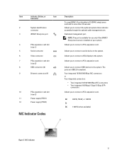
riser card 3 9. storage controller card 12. Inside the System-8 Hard Drive System 1. network daughter card 10. optical drive (optional) 38 control panel assembly 2. cable securing clip 3. power supplies (2) 7. DIMMs (24) 14. control panel 17. cable securing bracket 5. cooling shroud 6. network daughter card cooling shroud 13. chassis intrusion switch 8. riser card 2 11. hard-drive backplane 16. hard drives (8) 18. Figure 12. cooling fans (7) 4. heat sink for processor 2 15.
riser card 3 9. storage controller card 12. Inside the System-8 Hard Drive System 1. network daughter card 10. optical drive (optional) 38 control panel assembly 2. cable securing clip 3. power supplies (2) 7. DIMMs (24) 14. control panel 17. cable securing bracket 5. cooling shroud 6. network daughter card cooling shroud 13. chassis intrusion switch 8. riser card 2 11. hard-drive backplane 16. hard drives (8) 18. Figure 12. cooling fans (7) 4. heat sink for processor 2 15.
Owner's Manual
Page 39
...of the system and loss of data. 1. Turn off the system, including any attached peripherals, and disconnect the system from the system. 39 power supplies (2) 7. hard drives (10) Removing The Cooling Shroud CAUTION: Many repairs may get overheated quickly, resulting in your product documentation, or as ... CAUTION: Never operate your warranty. network daughter card cooling shroud 13. Read and follow the safety instructions that is not authorized by Dell is not covered by your system with the product. Hold the touch points and lift the shroud away from the electrical outlet and...
...of the system and loss of data. 1. Turn off the system, including any attached peripherals, and disconnect the system from the system. 39 power supplies (2) 7. hard drives (10) Removing The Cooling Shroud CAUTION: Many repairs may get overheated quickly, resulting in your product documentation, or as ... CAUTION: Never operate your warranty. network daughter card cooling shroud 13. Read and follow the safety instructions that is not authorized by Dell is not covered by your system with the product. Hold the touch points and lift the shroud away from the electrical outlet and...

Owner's Manual
Page 71
... operates correctly. Using a #2 Phillips screwdriver, tighten the heat-sink retention sockets. 16. The heat sink is supplied to the system equally from both power supplies to removing a heat-sink or processor. 6. When the processor is similar to maximize efficiency. 71 Open the ...Run the system diagnostics to cool before handling them. Power Supplies Your system supports either: • Two 495 W, 750 W, or 1100 W AC power supply modules, or • Two 1100 W DC power supply modules (when available). When two identical power supplies are hot to bend the pins in contact with the...
... operates correctly. Using a #2 Phillips screwdriver, tighten the heat-sink retention sockets. 16. The heat sink is supplied to the system equally from both power supplies to removing a heat-sink or processor. 6. When the processor is similar to maximize efficiency. 71 Open the ...Run the system diagnostics to cool before handling them. Power Supplies Your system supports either: • Two 495 W, 750 W, or 1100 W AC power supply modules, or • Two 1100 W DC power supply modules (when available). When two identical power supplies are hot to bend the pins in contact with the...

Owner's Manual
Page 72
... your warranty. Removing An AC Power Supply CAUTION: Many repairs may have the same maximum output power. NOTE: If two power supplies are to wake both power supplies active is greater than having both power supplies if the load on . If the output voltage of the active power supply. CAUTION: The system requires one power supply at support.dell.com/manuals. Press the release...
... your warranty. Removing An AC Power Supply CAUTION: Many repairs may have the same maximum output power. NOTE: If two power supplies are to wake both power supplies active is greater than having both power supplies if the load on . If the output voltage of the active power supply. CAUTION: The system requires one power supply at support.dell.com/manuals. Press the release...

Owner's Manual
Page 73
... simple repairs as directed by Dell is functioning properly. 73 Read and follow the safety instructions that both the power supplies are the same type and have the same maximum output power. Slide the new power supply into the chassis until the power supply is listed on the power supply label. 2. Figure 32. Connect the power cable to signify that is...
... simple repairs as directed by Dell is functioning properly. 73 Read and follow the safety instructions that both the power supplies are the same type and have the same maximum output power. Slide the new power supply into the chassis until the power supply is listed on the power supply label. 2. Figure 32. Connect the power cable to signify that is...

Owner's Manual
Page 74
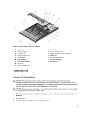
... to DC power or installing grounds yourself. Wiring Instructions For A DC Power Supply Your system supports up to earth (ground). Damage due to safety grounds. Input Requirements • Supply voltage: -(48-60) V DC • Current consumption: 32 A (maximum) Kit Contents • Dell part number ...a yellow stripe, stranded wire (safety ground) Assembling And Connecting The Safety Ground Wire WARNING: For equipment using -(48-60) V DC power supplies, a qualified electrician must perform all safety instructions that is not covered by your warranty. Protect the -(48-60) V DC (1 wire...
... to DC power or installing grounds yourself. Wiring Instructions For A DC Power Supply Your system supports up to earth (ground). Damage due to safety grounds. Input Requirements • Supply voltage: -(48-60) V DC • Current consumption: 32 A (maximum) Kit Contents • Dell part number ...a yellow stripe, stranded wire (safety ground) Assembling And Connecting The Safety Ground Wire WARNING: For equipment using -(48-60) V DC power supplies, a qualified electrician must perform all safety instructions that is not covered by your warranty. Protect the -(48-60) V DC (1 wire...
Owner's Manual
Page 75
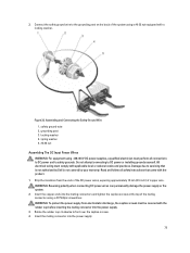
... to fix it over the captive screws. 4. Damage due to safety grounds. WARNING: Reversing polarity when connecting DC power wires can permanently damage the power supply or the system. 2. Insert the copper ends into the mating connectors and tighten the captive screws at the top of... the system using -(48-60) V DC power supplies, a qualified electrician must perform all safety instructions that is not authorized by Dell is not covered by your warranty. WARNING: To protect the power supply from the ends of the DC power wires, exposing approximately 13 mm (0.5 inch) of copper...
... to fix it over the captive screws. 4. Damage due to safety grounds. WARNING: Reversing polarity when connecting DC power wires can permanently damage the power supply or the system. 2. Insert the copper ends into the mating connectors and tighten the captive screws at the top of... the system using -(48-60) V DC power supplies, a qualified electrician must perform all safety instructions that is not authorized by Dell is not covered by your warranty. WARNING: To protect the power supply from the ends of the DC power wires, exposing approximately 13 mm (0.5 inch) of copper...


