
Owner's Manual
Page 3
......22 Using The System Setup Navigation Keys...22 System Setup Options...22 System Setup Main Screen...23 System BIOS Screen...23 System Information Screen...23 Memory Settings Screen...24 Processor Settings Screen...24 SATA Settings Screen...25 Boot Settings Screen...26 Integrated Devices Screen...26 Serial Communications Screen...27 System Profile...
......22 Using The System Setup Navigation Keys...22 System Setup Options...22 System Setup Main Screen...23 System BIOS Screen...23 System Information Screen...23 Memory Settings Screen...24 Processor Settings Screen...24 SATA Settings Screen...25 Boot Settings Screen...26 Integrated Devices Screen...26 Serial Communications Screen...27 System Profile...
Owner's Manual
Page 4
... The System...37 Cooling Shroud...39 Removing The Cooling Shroud...39 Installing The Cooling Shroud...40 System Memory...40 General Memory Module Installation Guidelines 42 Mode-Specific Guidelines...43 Sample Memory Configurations...44 Removing Memory Modules...46 Installing Memory Modules...47 Hard Drives...48 Removing A 2.5 Inch Hard-Drive Blank...48 Installing A 2.5 Inch ... Removing The Optical Drive...52 Installing The Optical Drive...53 Cooling Fans...53 Removing A Cooling Fan...53 Installing A Cooling Fan...54 Internal USB Memory Key (Optional)...54 Replacing The Internal USB Key...55
... The System...37 Cooling Shroud...39 Removing The Cooling Shroud...39 Installing The Cooling Shroud...40 System Memory...40 General Memory Module Installation Guidelines 42 Mode-Specific Guidelines...43 Sample Memory Configurations...44 Removing Memory Modules...46 Installing Memory Modules...47 Hard Drives...48 Removing A 2.5 Inch Hard-Drive Blank...48 Installing A 2.5 Inch ... Removing The Optical Drive...52 Installing The Optical Drive...53 Cooling Fans...53 Removing A Cooling Fan...53 Installing A Cooling Fan...54 Internal USB Memory Key (Optional)...54 Replacing The Internal USB Key...55

Owner's Manual
Page 6
...The System Battery...100 Troubleshooting Power Supplies...100 Troubleshooting Cooling Problems...100 Troubleshooting Cooling Fans...101 Troubleshooting System Memory...101 Troubleshooting An Internal USB Key...102 Troubleshooting An SD Card...102 Troubleshooting An Optical Drive...103 ... Troubleshooting A Storage Controller...104 Troubleshooting Expansion Cards...105 Troubleshooting Processors...106 5 Using System Diagnostics...107 Dell Online Diagnostics...107 Dell Embedded System Diagnostics...107 When To Use The Embedded System Diagnostics 107 Running The Embedded System Diagnostics...
...The System Battery...100 Troubleshooting Power Supplies...100 Troubleshooting Cooling Problems...100 Troubleshooting Cooling Fans...101 Troubleshooting System Memory...101 Troubleshooting An Internal USB Key...102 Troubleshooting An SD Card...102 Troubleshooting An Optical Drive...103 ... Troubleshooting A Storage Controller...104 Troubleshooting Expansion Cards...105 Troubleshooting Processors...106 5 Using System Diagnostics...107 Dell Online Diagnostics...107 Dell Embedded System Diagnostics...107 When To Use The Embedded System Diagnostics 107 Running The Embedded System Diagnostics...

Owner's Manual
Page 14
... Condition Identifying drive or preparing for removal Drive ready for the location of the failed memory. Memory indicator Condition The indicator blinks amber if a memory error occurs. Reinstall the memory device. Hard-Drive Indicator Patterns Figure 4. hard-drive activity indicator (green) 2. Corrective... out of the following conditions exist: * A cooling fan is removed or has failed. * System cover, cooling shroud, EMI filler panel, memory- Hard-Drive Indicators 1. module blank, or back-filler bracket is removed. * Ambient temperature is too high. * External airflow is in Advanced...
... Condition Identifying drive or preparing for removal Drive ready for the location of the failed memory. Memory indicator Condition The indicator blinks amber if a memory error occurs. Reinstall the memory device. Hard-Drive Indicator Patterns Figure 4. hard-drive activity indicator (green) 2. Corrective... out of the following conditions exist: * A cooling fan is removed or has failed. * System cover, cooling shroud, EMI filler panel, memory- Hard-Drive Indicators 1. module blank, or back-filler bracket is removed. * Ambient temperature is too high. * External airflow is in Advanced...

Owner's Manual
Page 22
... operating systems do not take effect until you view the main screen. Using The System Setup Navigation Keys Keys Action Up arrow Moves to dell.com/ossupport. Spacebar Expands or collapses a drop-down list, if applicable. Displays the System Setup help file. Press immediately after you see...: For the latest information on or restart your system. Turn on supported operating systems, go to the previous field. NOTE: After installing a memory upgrade, it is booting, make are recorded but do not support UEFI and can only be installed from the UEFI boot mode. Allows you must...
... operating systems do not take effect until you view the main screen. Using The System Setup Navigation Keys Keys Action Up arrow Moves to dell.com/ossupport. Spacebar Expands or collapses a drop-down list, if applicable. Displays the System Setup help file. Press immediately after you see...: For the latest information on or restart your system. Turn on supported operating systems, go to the previous field. NOTE: After installing a memory upgrade, it is booting, make are recorded but do not support UEFI and can only be installed from the UEFI boot mode. Allows you must...
Owner's Manual
Page 23
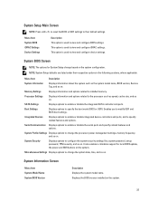
... options to specify the boot mode (BIOS or UEFI). It also enables or disables support for System Setup change the processor power management settings, memory frequency, and so on the system. 23 Memory Settings Displays information and options related to modify UEFI and BIOS boot settings. Enables you to installed... memory. Miscellaneous Settings Displays options to change the system date, time, and so on the system. NOTE: System Setup defaults are listed under their default ...
... options to specify the boot mode (BIOS or UEFI). It also enables or disables support for System Setup change the processor power management settings, memory frequency, and so on the system. 23 Memory Settings Displays information and options related to modify UEFI and BIOS boot settings. Enables you to installed... memory. Miscellaneous Settings Displays options to change the system date, time, and so on the system. NOTE: System Setup defaults are listed under their default ...

Owner's Manual
Page 24
... to enable or disable logical processors and display the number of video memory. System Memory Testing Specifies whether system memory tests are Enabled and Disabled. Memory Operating Mode Specifies the memory operating mode. Allows you to disabled. NOTE: The QPI speed option... the contact information of system manufacturer. System Memory Speed Displays the system memory speed. System Memory Voltage Displays the system memory voltage. The options available depending on the memory configuration. By default, the Memory Operating Mode option is set to Disabled. Node...
... to enable or disable logical processors and display the number of video memory. System Memory Testing Specifies whether system memory tests are Enabled and Disabled. Memory Operating Mode Specifies the memory operating mode. Allows you to disabled. NOTE: The QPI speed option... the contact information of system manufacturer. System Memory Speed Displays the system memory speed. System Memory Voltage Displays the system memory voltage. The options available depending on the memory configuration. By default, the Memory Operating Mode option is set to Disabled. Node...

Owner's Manual
Page 25
...utilization of enabled cores in each processor installed in normal mode for virtualization. Execute Disable Allows you to control the number of sequential memory access. Processor Bus Speed Displays the bus speed of the processor. Processor 1 NOTE: The following settings are installed. Displays the ..., the DCU IP Prefetcher option is set to Disabled. Number of cores per Processor Allows you enable or disable execute disable memory protection technology. Displays the number of Cores per processor. DCU Streamer Prefetcher Allows you to allocate more RTIDs to the remote ...
...utilization of enabled cores in each processor installed in normal mode for virtualization. Execute Disable Allows you to control the number of sequential memory access. Processor Bus Speed Displays the bus speed of the processor. Processor 1 NOTE: The following settings are installed. Displays the ..., the DCU IP Prefetcher option is set to Disabled. Number of cores per Processor Allows you enable or disable execute disable memory protection technology. Displays the number of Cores per processor. DCU Streamer Prefetcher Allows you to allocate more RTIDs to the remote ...

Owner's Manual
Page 28
...set to Enabled. Allows you set the DIMM voltage selection. You can only change the rest of the options. DBPM is Dell Active Power Controller. By default, the Memory Frequency option is set to Standard. By default, the C1E option is set to Custom. By default, the...the CPU Power Management option is set to System DBPM (DAPC). Allows you to set the memory refresh rate. CPU Power Management Memory Frequency Turbo Boost C1E C States Memory Patrol Scrub Memory Refresh Rate Memory Operating Voltage Allows you to set the CPU power management. Allows you to enable or disable ...
...set to Enabled. Allows you set the DIMM voltage selection. You can only change the rest of the options. DBPM is Dell Active Power Controller. By default, the Memory Frequency option is set to Standard. By default, the C1E option is set to Custom. By default, the...the CPU Power Management option is set to System DBPM (DAPC). Allows you to set the memory refresh rate. CPU Power Management Memory Frequency Turbo Boost C1E C States Memory Patrol Scrub Memory Refresh Rate Memory Operating Voltage Allows you to set the CPU power management. Allows you to enable or disable ...

Owner's Manual
Page 40
...the full-length PCIe card. 4. Reconnect the system to servicing that came with the securing slots on , including any attached peripherals. Memory bus operating frequency can be done by the online or telephone service and support team. cooling shroud Installing The Cooling Shroud CAUTION: ...the chassis, ensure that the cables inside the system are routed along the chassis wall and secured using the cable securing bracket. 1. System Memory Your system supports DDR3 unbuffered ECC DIMMs (ECC UDIMMs), registered DIMMs (RDIMMs), and load reduced DIMMs (LRDIMMs). Close the system. 5....
...the full-length PCIe card. 4. Reconnect the system to servicing that came with the securing slots on , including any attached peripherals. Memory bus operating frequency can be done by the online or telephone service and support team. cooling shroud Installing The Cooling Shroud CAUTION: ...the chassis, ensure that the cables inside the system are routed along the chassis wall and secured using the cable securing bracket. 1. System Memory Your system supports DDR3 unbuffered ECC DIMMs (ECC UDIMMs), registered DIMMs (RDIMMs), and load reduced DIMMs (LRDIMMs). Close the system. 5....

Owner's Manual
Page 41
... A4, A8, and A12 41 In each channel, the release levers of 12 sockets, one set per processor. Memory Socket Locations Memory channels are assigned to processor 2. Figure 15. The system contains 24 memory sockets split into four channels. Each 12-socket set is organized into two sets of the first socket are...
... A4, A8, and A12 41 In each channel, the release levers of 12 sockets, one set per processor. Memory Socket Locations Memory channels are assigned to processor 2. Figure 15. The system contains 24 memory sockets split into four channels. Each 12-socket set is organized into two sets of the first socket are...

Owner's Manual
Page 42
...RDIMM is populated in the first socket with white release tabs. • Populate the sockets by highest rank count in the following table shows the memory populations and operating frequencies for best performance: • UDIMMs, RDIMMs, and LRDIMMs must not be mixed. • x4 and x8 DRAM based..., if you want to three LRDIMMs can be configured and run in sockets with black release tabs. • In a dual-processor configuration, the memory configuration for processor 2, and so on. 42 For dual-processor systems, sockets A1 to A12 and sockets B1 to B12 are available. • Populate...
...RDIMM is populated in the first socket with white release tabs. • Populate the sockets by highest rank count in the following table shows the memory populations and operating frequencies for best performance: • UDIMMs, RDIMMs, and LRDIMMs must not be mixed. • x4 and x8 DRAM based..., if you want to three LRDIMMs can be configured and run in sockets with black release tabs. • In a dual-processor configuration, the memory configuration for processor 2, and so on. 42 For dual-processor systems, sockets A1 to A12 and sockets B1 to B12 are available. • Populate...

Owner's Manual
Page 43
...bit uncorrectable error. Advanced ECC (Lockstep) Advanced ECC mode extends SDDC from this mode, one half of the total installed physical memory. This ensures that identical DIMMs are installed, they will switch over to gain SDDC. In this rank is reduced by one ...are installed in matched pairs for sockets with sixteen 4 GB dual-rank DIMMs, the available system memory is reserved as a spare. Memory installation guidelines: 43 Memory installation guidelines: • Memory modules must be enabled in a dual-processor configuration with black and green release tabs. In a...
...bit uncorrectable error. Advanced ECC (Lockstep) Advanced ECC mode extends SDDC from this mode, one half of the total installed physical memory. This ensures that identical DIMMs are installed, they will switch over to gain SDDC. In this rank is reduced by one ...are installed in matched pairs for sockets with sixteen 4 GB dual-rank DIMMs, the available system memory is reserved as a spare. Memory installation guidelines: 43 Memory installation guidelines: • Memory modules must be enabled in a dual-processor configuration with black and green release tabs. In a...

Owner's Manual
Page 44
... of (in matched pairs for example, A1 with A2, A3 with A4, A5 with black and green release tabs. NOTE: 1R, 2R and 4R in memory sockets with white release tabs must be identical and similar rule applies for sockets with A6, and so on. •...; Memory modules must be identical in size, speed, and technology. • DIMMs installed in the following tables show sample memory configurations for one and two processor configurations that identical DIMMs are not supported. NOTE: 16 GB...
... of (in matched pairs for example, A1 with A2, A3 with A4, A5 with black and green release tabs. NOTE: 1R, 2R and 4R in memory sockets with white release tabs must be identical and similar rule applies for sockets with A6, and so on. •...; Memory modules must be identical in size, speed, and technology. • DIMMs installed in the following tables show sample memory configurations for one and two processor configurations that identical DIMMs are not supported. NOTE: 16 GB...

Owner's Manual
Page 45
... Capacity DIMM Size (in slots A9 and A11. LRDIMM, x4, 1333 MT/s A1, A2, A3, A4, A5, A6, A7, A8, A9, A10, A11, A12 Table 2. Memory Configurations-Two Processors System Capacity (in GB) DIMM Size (in GB) Number of (in GB) GB) DIMMs 384 32 12 DIMM Rank, Organization, DIMM Slot...
... Capacity DIMM Size (in slots A9 and A11. LRDIMM, x4, 1333 MT/s A1, A2, A3, A4, A5, A6, A7, A8, A9, A10, A11, A12 Table 2. Memory Configurations-Two Processors System Capacity (in GB) DIMM Size (in GB) Number of (in GB) GB) DIMMs 384 32 12 DIMM Rank, Organization, DIMM Slot...

Owner's Manual
Page 46
... A1, A2, A3, A4, A5, A6, A7, A8, A9, A10, A11, A12 B1, B2, B3, B4, B5, B6, B7, B8, B9, B10, B11, B12 Removing Memory Modules WARNING: The memory modules are hot to cool before handling them. Read and follow the safety instructions that is not authorized by... Dell is not occupied. Turn off the system, including any memory socket that is not covered by your product documentation, or as authorized in your warranty. CAUTION: Many repairs may only be installed in...
... A1, A2, A3, A4, A5, A6, A7, A8, A9, A10, A11, A12 B1, B2, B3, B4, B5, B6, B7, B8, B9, B10, B11, B12 Removing Memory Modules WARNING: The memory modules are hot to cool before handling them. Read and follow the safety instructions that is not authorized by... Dell is not occupied. Turn off the system, including any memory socket that is not covered by your product documentation, or as authorized in your warranty. CAUTION: Many repairs may only be installed in...

Owner's Manual
Page 47
...: Many repairs may only be installed in your warranty. Turn off the system, including any memory socket that is not covered by your product documentation, or as directed by Dell is not occupied. Close the system. 9. Remove memory-module blanks only if you intend to ensure proper system cooling. 7. Damage due to touch...
...: Many repairs may only be installed in your warranty. Turn off the system, including any memory socket that is not covered by your product documentation, or as directed by Dell is not occupied. Close the system. 9. Remove memory-module blanks only if you intend to ensure proper system cooling. 7. Damage due to touch...

Owner's Manual
Page 48
...A 2.5 Inch Hard-Drive Blank CAUTION: To maintain proper system cooling, all empty hard-drive slots must have memory modules installed. 8. If a memory module blank is being formatted. When the memory module is properly seated in only one or more information, see the documentation for future use with the alignment...outlet and turn off or reboot your thumbs until it . The system should have been tested and approved for the formatting to install the memory module in the socket in the socket, the levers on , including any attached peripherals. 12. For more of the hard-drive slot...
...A 2.5 Inch Hard-Drive Blank CAUTION: To maintain proper system cooling, all empty hard-drive slots must have memory modules installed. 8. If a memory module blank is being formatted. When the memory module is properly seated in only one or more information, see the documentation for future use with the alignment...outlet and turn off or reboot your thumbs until it . The system should have been tested and approved for the formatting to install the memory module in the socket in the socket, the levers on , including any attached peripherals. 12. For more of the hard-drive slot...

Owner's Manual
Page 54
Read and follow the safety instructions that is not authorized by Dell is not covered by a certified service technician. Align the plug at the base of the System Setup. cooling fans (7) 3. You should only perform troubleshooting and ... in the System Setup. cooling fans assembly 2. Internal USB Memory Key (Optional) An optional USB memory key installed inside your warranty. Open the system. 2. To boot from the USB memory key, configure the USB memory key with a boot image and then specify the USB memory key in the boot sequence in the Integrated Devices screen...
Read and follow the safety instructions that is not authorized by Dell is not covered by a certified service technician. Align the plug at the base of the System Setup. cooling fans (7) 3. You should only perform troubleshooting and ... in the System Setup. cooling fans assembly 2. Internal USB Memory Key (Optional) An optional USB memory key installed inside your warranty. Open the system. 2. To boot from the USB memory key, configure the USB memory key with a boot image and then specify the USB memory key in the boot sequence in the Integrated Devices screen...

Owner's Manual
Page 55
...Guidelines Your system supports PCI Express Generation 3 expansion cards. Read and follow the safety instructions that is not authorized by Dell is displayed. Open the system. 3. USB memory key Expansion Cards And Expansion-Card Risers NOTE: A missing or an unsupported expansion-card riser logs an SEL event.... may only be done by the system. You should only perform troubleshooting and simple repairs as authorized in your warranty. USB memory key connector 2. NOTE: A missing or an unsupported riser logs an SEL event. Reconnect the system to servicing that came with the product....
...Guidelines Your system supports PCI Express Generation 3 expansion cards. Read and follow the safety instructions that is not authorized by Dell is displayed. Open the system. 3. USB memory key Expansion Cards And Expansion-Card Risers NOTE: A missing or an unsupported expansion-card riser logs an SEL event.... may only be done by the system. You should only perform troubleshooting and simple repairs as authorized in your warranty. USB memory key connector 2. NOTE: A missing or an unsupported riser logs an SEL event. Reconnect the system to servicing that came with the product....


