
Getting Started Guide
Page 10
...supported on twelve-hard-drive systems. • Citrix® XenServer™ Enterprise (Version 5.5) NOTE: Twelve-hard-drive systems support Citrix XenServer Enterprise (Version 6.0). • Citrix Essentials for XenServer Enterprise (Version 5.5) NOTE: For the latest information on support.dell.com/manuals and ... updates, and system components that shipped with your system, including those pertaining to troubleshoot the system and install or replace system components. Other Information You May Need WARNING: See the safety and regulatory information that you do not understand ...
...supported on twelve-hard-drive systems. • Citrix® XenServer™ Enterprise (Version 5.5) NOTE: Twelve-hard-drive systems support Citrix XenServer Enterprise (Version 6.0). • Citrix Essentials for XenServer Enterprise (Version 5.5) NOTE: For the latest information on support.dell.com/manuals and ... updates, and system components that shipped with your system, including those pertaining to troubleshoot the system and install or replace system components. Other Information You May Need WARNING: See the safety and regulatory information that you do not understand ...

Hardware Owner's Manual
Page 6
... a Hard Drive From a Hard-Drive Carrier 98 Installing a Hard Drive Into a Hard-Drive Carrier 98 Internal Hard Drives 99 Removing an Internal Hard Drive Bay 99 Installing an Internal Hard Drive Bay 101 Removing an Internal Hard Drive From the Internal Hard-Drive Bay 101 Installing a Hard Drive Into a Hard-Drive Bay 102 Optical Drive (Optional 103 Removing an Optical Drive 103 Installing an Optical Drive 104 Cooling Fans 105 Removing a Cooling Fan 105 Replacing a Cooling...
... a Hard Drive From a Hard-Drive Carrier 98 Installing a Hard Drive Into a Hard-Drive Carrier 98 Internal Hard Drives 99 Removing an Internal Hard Drive Bay 99 Installing an Internal Hard Drive Bay 101 Removing an Internal Hard Drive From the Internal Hard-Drive Bay 101 Installing a Hard Drive Into a Hard-Drive Bay 102 Optical Drive (Optional 103 Removing an Optical Drive 103 Installing an Optical Drive 104 Cooling Fans 105 Removing a Cooling Fan 105 Replacing a Cooling...

Hardware Owner's Manual
Page 8
... Module (Optional 154 Removing the Front-Panel IO Module (Twelve-Hard-Drive System 154 Installing the Front-Panel IO Module (Twelve-Hard-Drive System 156 SAS Backplane 156 Removing the SAS Backplane 156 Installing the SAS Backplane 160 Power Distribution Board 161 Removing the Power Distribution Board . . . . . 161 Replacing the Power Distribution Board . . . . . 164 8 Contents
... Module (Optional 154 Removing the Front-Panel IO Module (Twelve-Hard-Drive System 154 Installing the Front-Panel IO Module (Twelve-Hard-Drive System 156 SAS Backplane 156 Removing the SAS Backplane 156 Installing the SAS Backplane 160 Power Distribution Board 161 Removing the Power Distribution Board . . . . . 161 Replacing the Power Distribution Board . . . . . 164 8 Contents

Hardware Owner's Manual
Page 51
... or the requested sector is no device connected Information only. SATA Port x device not found The operating system cannot Replace the optical medium, read from the hard drive, USB medium, or USB optical drive, or USB device, device. single rank or dual rank DIMM in the clear position (pins 1 and 3) and reboot the system...
... or the requested sector is no device connected Information only. SATA Port x device not found The operating system cannot Replace the optical medium, read from the hard drive, USB medium, or USB optical drive, or USB device, device. single rank or dual rank DIMM in the clear position (pins 1 and 3) and reboot the system...

Hardware Owner's Manual
Page 52
... appropriate drive(s) installed in BIOS. If memory has been added or removed, this message is informative and can be populated across slots. If memory has not been added or removed, check the SEL to determine if single-bit or multi-bit errors were detected and replace the... properly connected. The memory configuration does not match the setting in your system. See "Troubleshooting a USB Device" on page 170 or "Troubleshooting a Hard Drive" on page 199. The BIOS setting has been disabled. See "System Memory" on page 177. 52 About Your System Sparing mode disabled. See ...
... appropriate drive(s) installed in BIOS. If memory has been added or removed, this message is informative and can be populated across slots. If memory has not been added or removed, check the SEL to determine if single-bit or multi-bit errors were detected and replace the... properly connected. The memory configuration does not match the setting in your system. See "Troubleshooting a USB Device" on page 170 or "Troubleshooting a Hard Drive" on page 199. The BIOS setting has been disabled. See "System Memory" on page 177. 52 About Your System Sparing mode disabled. See ...

Hardware Owner's Manual
Page 58
... page 179, "Troubleshooting an Optical Drive" on page 180, and "Troubleshooting a Hard Drive" on selected drive Faulty USB device, USB medium, optical drive assembly, hard drive, or hard drive subsystem. NOTE: For the full name of an abbreviation or acronym used in this table, see the "Glossary" on page 201. 58 About Your System Replace the USB medium or device.
... page 179, "Troubleshooting an Optical Drive" on page 180, and "Troubleshooting a Hard Drive" on selected drive Faulty USB device, USB medium, optical drive assembly, hard drive, or hard drive subsystem. NOTE: For the full name of an abbreviation or acronym used in this table, see the "Glossary" on page 201. 58 About Your System Replace the USB medium or device.

Hardware Owner's Manual
Page 86
Figure 3-3. Removing the Front Bezel 1 Using the system key, unlock the bezel. 2 Lift the release latch next to the power button, optical drive, and hard drive(s). Front Bezel (Optional) A lock on the bezel restricts access to the key lock. 3 Rotate the left end of the bezel away from the front panel. 4 Unhook the right end of the bezel and pull the bezel away from the system. Removing and Replacing the Front Bezel 3 2 1 1 release latch 3 bezel 4 2 keylock 4 hinge tab 86 Installing System Components The LCD panel and navigation buttons are accessible through the front bezel.
Figure 3-3. Removing the Front Bezel 1 Using the system key, unlock the bezel. 2 Lift the release latch next to the power button, optical drive, and hard drive(s). Front Bezel (Optional) A lock on the bezel restricts access to the key lock. 3 Rotate the left end of the bezel away from the front panel. 4 Unhook the right end of the bezel and pull the bezel away from the system. Removing and Replacing the Front Bezel 3 2 1 1 release latch 3 bezel 4 2 keylock 4 hinge tab 86 Installing System Components The LCD panel and navigation buttons are accessible through the front bezel.

Hardware Owner's Manual
Page 88
Figure 3-4. Removing and Replacing the System Cover (Eight-Hard-Drive System) 2 1 1 system cover latch 2 latch release lock 88 Installing System Components
Figure 3-4. Removing and Replacing the System Cover (Eight-Hard-Drive System) 2 1 1 system cover latch 2 latch release lock 88 Installing System Components

Hardware Owner's Manual
Page 89
Figure 3-5. See Figure 3-4 and Figure 3-5. 3 Slide the cover towards the front of the chassis. Installing System Components 89 Removing and Replacing the System Cover (Twelve-Hard-Drive System) 2 1 1 system cover latch 2 latch release lock Closing the System 1 Lift the latch on the system cover. 2 Place the cover onto the chassis and offset ...
Figure 3-5. See Figure 3-4 and Figure 3-5. 3 Slide the cover towards the front of the chassis. Installing System Components 89 Removing and Replacing the System Cover (Twelve-Hard-Drive System) 2 1 1 system cover latch 2 latch release lock Closing the System 1 Lift the latch on the system cover. 2 Place the cover onto the chassis and offset ...

Hardware Owner's Manual
Page 96
...: If you are not replacing the hard drive, remove the drive from the peripherals. 2 Open the system. See "Opening the System" on page 87. 3 Remove the existing hard-drive bracket by your product documentation, or as directed by a certified service technician. Read and follow the safety instructions that is not authorized by Dell is not covered by...
...: If you are not replacing the hard drive, remove the drive from the peripherals. 2 Open the system. See "Opening the System" on page 87. 3 Remove the existing hard-drive bracket by your product documentation, or as directed by a certified service technician. Read and follow the safety instructions that is not authorized by Dell is not covered by...

Hardware Owner's Manual
Page 97
...and reboot the system. See the documentation that the hard drive's controller is enabled. For information on installing a SAS controller card, see "Installing an Expansion Card" on installing any software required for instructions on page 124. 7 Replace the system cover. See "Entering the System Setup ...Program" on the card edge. See Figure 6-1. • If connecting to a SAS RAID controller card (SAS or SATA hard drives), connect the data cable to the electrical outlet and...
...and reboot the system. See the documentation that the hard drive's controller is enabled. For information on installing a SAS controller card, see "Installing an Expansion Card" on installing any software required for instructions on page 124. 7 Replace the system cover. See "Entering the System Setup ...Program" on the card edge. See Figure 6-1. • If connecting to a SAS RAID controller card (SAS or SATA hard drives), connect the data cable to the electrical outlet and...

Hardware Owner's Manual
Page 103
... twelve-hard-drive systems support only an external USB optical drive. Note the routing of the optical drive cable underneath the tabs on page 87. 4 Disconnect the optical drive cable from the system board and drive. See Figure 3-14. 6 If you replace them from the back of the system. NOTE: DVD devices are not adding a new optical drive, replace...
... twelve-hard-drive systems support only an external USB optical drive. Note the routing of the optical drive cable underneath the tabs on page 87. 4 Disconnect the optical drive cable from the system board and drive. See Figure 3-14. 6 If you replace them from the back of the system. NOTE: DVD devices are not adding a new optical drive, replace...
Hardware Owner's Manual
Page 105
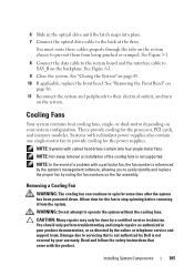
.... Damage due to their electrical outlets, and turn on the backplane. Read and follow the safety instructions that is not authorized by Dell is not covered by your system configuration. or dual-motor depending on the fan assembly. Systems with redundant power supplies also contain one...through the tabs on page 89. 10 If applicable, replace the front bezel. NOTE: Systems with the product. See "Removing the Front Bezel" on page 86. 11 Reconnect the system and peripherals to servicing that came with cabled hard drives contain only four single-motor fans. CAUTION: Many repairs...
.... Damage due to their electrical outlets, and turn on the backplane. Read and follow the safety instructions that is not authorized by Dell is not covered by your system configuration. or dual-motor depending on the fan assembly. Systems with redundant power supplies also contain one...through the tabs on page 89. 10 If applicable, replace the front bezel. NOTE: Systems with the product. See "Removing the Front Bezel" on page 86. 11 Reconnect the system and peripherals to servicing that came with cabled hard drives contain only four single-motor fans. CAUTION: Many repairs...
Hardware Owner's Manual
Page 107
Removing and Replacing a Fan (Eight-Hard-Drive System) 2 1 3 1 fans (5) 3 fan cable 2 release tab Installing System Components 107 Figure 3-15.
Removing and Replacing a Fan (Eight-Hard-Drive System) 2 1 3 1 fans (5) 3 fan cable 2 release tab Installing System Components 107 Figure 3-15.
Hardware Owner's Manual
Page 108
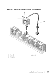
Figure 3-16. Removing and Replacing a Fan (Twelve-Hard-Drive System) 2 1 3 1 fans (5) 3 fan cable 2 release tab 108 Installing System Components
Figure 3-16. Removing and Replacing a Fan (Twelve-Hard-Drive System) 2 1 3 1 fans (5) 3 fan cable 2 release tab 108 Installing System Components

Hardware Owner's Manual
Page 109
...power connector on the system board. 4 Route the power cable through the guides on page 112". NOTE: For twelve-hard-drive systems, first replace the internal hard-drive carrier and bay. See "Installing the Power Supply Blank" on the chassis. Power Supplies Your system supports the following power... up by the remaining power supply. See "Installing an Internal Hard Drive Bay" on , including any attached peripherals. If two power supplies are installed, the second power supply provides hot-swappable, power redundancy. Replacing a Cooling Fan 1 Align the fan module so that the side...
...power connector on the system board. 4 Route the power cable through the guides on page 112". NOTE: For twelve-hard-drive systems, first replace the internal hard-drive carrier and bay. See "Installing the Power Supply Blank" on the chassis. Power Supplies Your system supports the following power... up by the remaining power supply. See "Installing an Internal Hard Drive Bay" on , including any attached peripherals. If two power supplies are installed, the second power supply provides hot-swappable, power redundancy. Replacing a Cooling Fan 1 Align the fan module so that the side...

Hardware Owner's Manual
Page 114
...tighten the screws to systems with cabled hard drives only. 1 Open the system. System Memory Your system supports DDR3 registered DIMMs (RDIMMs) or unbuffered ECC DIMMs (UDIMMs). The system contains eight memory sockets split into a power outlet. 6 Replace the system cover. Each four-socket ...power supply with white release levers. 114 Installing System Components Single and dual-rank DIMMs can be 1067- 1 bracket 3 power supply 5 optical drive power cable 7 SATA power cable 2 screws (2) 4 power cable 8 pins 6 power cable 24 pins Installing a Non-Redundant Power Supply NOTE...
...tighten the screws to systems with cabled hard drives only. 1 Open the system. System Memory Your system supports DDR3 registered DIMMs (RDIMMs) or unbuffered ECC DIMMs (UDIMMs). The system contains eight memory sockets split into a power outlet. 6 Replace the system cover. Each four-socket ...power supply with white release levers. 114 Installing System Components Single and dual-rank DIMMs can be 1067- 1 bracket 3 power supply 5 optical drive power cable 7 SATA power cable 2 screws (2) 4 power cable 8 pins 6 power cable 24 pins Installing a Non-Redundant Power Supply NOTE...

Hardware Owner's Manual
Page 149
...the cable. See "Closing the System" on the system and attached peripherals. 5 If applicable, replace the front bezel. Damage due to the power source and turn on page 89. 4 Reconnect the system... to servicing that is not authorized by Dell is not covered by the online or telephone service and support team. Read and follow... Removing the Control-Panel Module-LED (Twelve-Hard-Drive System) CAUTION: Many repairs may only be done by using the pull tab. Installing the Control Panel Assembly (Four-Hard-Drive System) 1 Install the control panel board ...
...the cable. See "Closing the System" on the system and attached peripherals. 5 If applicable, replace the front bezel. Damage due to the power source and turn on page 89. 4 Reconnect the system... to servicing that is not authorized by Dell is not covered by the online or telephone service and support team. Read and follow... Removing the Control-Panel Module-LED (Twelve-Hard-Drive System) CAUTION: Many repairs may only be done by using the pull tab. Installing the Control Panel Assembly (Four-Hard-Drive System) 1 Install the control panel board ...

Hardware Owner's Manual
Page 151
...peripherals, and disconnect the system from the control panel board. See "Opening the System" on the system and attached peripherals. 6 If applicable, replace the front bezel. See "Closing the System" on page 89. 5 Reconnect the system to servicing that came with the three Torx screws. ... and simple repairs as authorized in your warranty. Read and follow the safety instructions that is not authorized by Dell is applicable only to the eight-hard-drive systems. NOTE: The control panel assembly consists of the display and slide the blade across the bottom to remove...
...peripherals, and disconnect the system from the control panel board. See "Opening the System" on the system and attached peripherals. 6 If applicable, replace the front bezel. See "Closing the System" on page 89. 5 Reconnect the system to servicing that came with the three Torx screws. ... and simple repairs as authorized in your warranty. Read and follow the safety instructions that is not authorized by Dell is applicable only to the eight-hard-drive systems. NOTE: The control panel assembly consists of the display and slide the blade across the bottom to remove...

Hardware Owner's Manual
Page 154
...Phillips screws. Front-Panel IO Module (Optional) Removing the Front-Panel IO Module (Twelve-Hard-Drive System) CAUTION: Many repairs may only be done by the online or telephone service and... a certified service technician. Read and follow the safety instructions that is not authorized by Dell is not covered by your product documentation, or as authorized in the system chassis and secure... module cable to the power source and turn on the system and attached peripherals. 7 If applicable, replace the front bezel. Damage due to the module and remove the bracket. 5 Unlatch and disconnect the...
...Phillips screws. Front-Panel IO Module (Optional) Removing the Front-Panel IO Module (Twelve-Hard-Drive System) CAUTION: Many repairs may only be done by the online or telephone service and... a certified service technician. Read and follow the safety instructions that is not authorized by Dell is not covered by your product documentation, or as authorized in the system chassis and secure... module cable to the power source and turn on the system and attached peripherals. 7 If applicable, replace the front bezel. Damage due to the module and remove the bracket. 5 Unlatch and disconnect the...


