
Glossary
Page 1
... the management information utilized by an administrator, for communications between the components of a program or data file. It provides mapping techniques for quick data retrieval. Dell™ Glossary NOTE: For additional information on storage terminology, visit the Storage Networking Industry Association's website at www.snia.org and click on a regular basis.... backup - cache - CA - American National Standards Institute. Your system contains an expansion bus that is located. Alternating current. Celsius. A - A module that includes power supplies and fans.
... the management information utilized by an administrator, for communications between the components of a program or data file. It provides mapping techniques for quick data retrieval. Dell™ Glossary NOTE: For additional information on storage terminology, visit the Storage Networking Industry Association's website at www.snia.org and click on a regular basis.... backup - cache - CA - American National Standards Institute. Your system contains an expansion bus that is located. Alternating current. Celsius. A - A module that includes power supplies and fans.

Glossary
Page 3
...physical interface between the processor and the main memory (RAM). Gigabyte(s); 1024 megabytes or 1,073,741,824 bytes. Integrated drive electronics. Gravities. Integrated Dell Remote Access Controller. A remote access controller that can be differentiated from computational activity. The file system structure used primarily with high-speed peripherals. Internet... in an expansion card. Internet Protocol. F - InfiniBand offers point-to insert or install a device, typically a hard drive or an internal cooling fan, into the host system while the system is an output device.
...physical interface between the processor and the main memory (RAM). Gigabyte(s); 1024 megabytes or 1,073,741,824 bytes. Integrated drive electronics. Gravities. Integrated Dell Remote Access Controller. A remote access controller that can be differentiated from computational activity. The file system structure used primarily with high-speed peripherals. Internet... in an expansion card. Internet Protocol. F - InfiniBand offers point-to insert or install a device, typically a hard drive or an internal cooling fan, into the host system while the system is an output device.

Hardware Owner's Manual
Page 6
... a Hard Drive Into a Hard-Drive Bay 102 Optical Drive (Optional 103 Removing an Optical Drive 103 Installing an Optical Drive 104 Cooling Fans 105 Removing a Cooling Fan 105 Replacing a Cooling Fan 109 Power Supplies 109 Removing a Redundant Power Supply 110 Installing a Redundant Power Supply 111 Removing the Power Supply Blank 112 Installing the...
... a Hard Drive Into a Hard-Drive Bay 102 Optical Drive (Optional 103 Removing an Optical Drive 103 Installing an Optical Drive 104 Cooling Fans 105 Removing a Cooling Fan 105 Replacing a Cooling Fan 109 Power Supplies 109 Removing a Redundant Power Supply 110 Installing a Redundant Power Supply 111 Removing the Power Supply Blank 112 Installing the...
Hardware Owner's Manual
Page 9
... a NIC 171 Troubleshooting a Wet System 172 Troubleshooting a Damaged System 174 Troubleshooting the System Battery 174 Troubleshooting Power Supplies 175 Troubleshooting System Cooling Problems 176 Troubleshooting a Fan 176 Troubleshooting System Memory 177 Troubleshooting an Internal USB Key 179 Troubleshooting an Optical Drive 180 Troubleshooting a Hard Drive 181 Contents 9
... a NIC 171 Troubleshooting a Wet System 172 Troubleshooting a Damaged System 174 Troubleshooting the System Battery 174 Troubleshooting Power Supplies 175 Troubleshooting System Cooling Problems 176 Troubleshooting a Fan 176 Troubleshooting System Memory 177 Troubleshooting an Internal USB Key 179 Troubleshooting an Optical Drive 180 Troubleshooting a Hard Drive 181 Contents 9

Hardware Owner's Manual
Page 31
... the processor(s). If the problem persists, see "Getting Help" on page 199. See "Troubleshooting System Memory" on page 186. Check fan. fan redundant. If the problem persists, see "Getting Help" on page 199. One of the intended operating range. If the problem persists... voltage regulators has failed. Check LCD for additional scrolling messages. Power cycle AC. E122E On-board regulator failed. See "Troubleshooting a Fan" on page 176. Code Text Causes Corrective Actions E122A CPU # VTT Regulator failure. Specified processor VTT voltage regulator has failed. E122C...
... the processor(s). If the problem persists, see "Getting Help" on page 199. See "Troubleshooting System Memory" on page 186. Check fan. fan redundant. If the problem persists, see "Getting Help" on page 199. One of the intended operating range. If the problem persists... voltage regulators has failed. Check LCD for additional scrolling messages. Power cycle AC. E122E On-board regulator failed. See "Troubleshooting a Fan" on page 176. Code Text Causes Corrective Actions E122A CPU # VTT Regulator failure. Specified processor VTT voltage regulator has failed. E122C...

Hardware Owner's Manual
Page 41
... SEL entry. Turn off the system and disconnect it can provide, configuration. Removing LCD Status Messages For faults associated with sensors, such as temperature, voltage, fans, and so on the LCD can perform this table, see the "Glossary" on page 201. For example, if temperature for the system. • Power cycle...
... SEL entry. Turn off the system and disconnect it can provide, configuration. Removing LCD Status Messages For faults associated with sensors, such as temperature, voltage, fans, and so on the LCD can perform this table, see the "Glossary" on page 201. For example, if temperature for the system. • Power cycle...
Hardware Owner's Manual
Page 59
... information about system diagnostics. Diagnostics Messages The system diagnostic utilities may issue messages if you may lose all data on page 190 for drive, temperature, fan, and power conditions. NOTE: Warning messages are generated by typing y (yes) or n (no). Alert messages include information, status, warning, and failure messages for more information...
... information about system diagnostics. Diagnostics Messages The system diagnostic utilities may issue messages if you may lose all data on page 190 for drive, temperature, fan, and power conditions. NOTE: Warning messages are generated by typing y (yes) or n (no). Alert messages include information, status, warning, and failure messages for more information...
Hardware Owner's Manual
Page 64
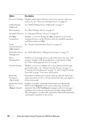
..., cache size, and so on page 70. See "Processor Settings Screen" on 101- Report Keyboard Errors (Report default) Enables or disables reporting of the processor, fans, and memory modules with the NumLock mode activated on page 66. Keyboard NumLock (On default) Determines whether your system starts up with preconfigured or customized...
..., cache size, and so on page 70. See "Processor Settings Screen" on 101- Report Keyboard Errors (Report default) Enables or disables reporting of the processor, fans, and memory modules with the NumLock mode activated on page 66. Keyboard NumLock (On default) Determines whether your system starts up with preconfigured or customized...
Hardware Owner's Manual
Page 71
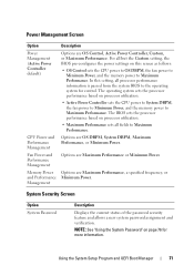
... processor performance information is passed from the system BIOS to Maximum Performance. Memory Power Options are Maximum Performance or Minimum Power. Fan Power and Performance Management Options are Maximum Performance, a specified frequency, or and Performance Minimum Power. Management System Security Screen Option...See "Using the System Password" on processor utilization. • Active Power Controller sets the CPU power to System DBPM, the fan power to Minimum Power, and the memory power to Maximum Performance. Using the System Setup Program and UEFI Boot Manager 71 The...
... processor performance information is passed from the system BIOS to Maximum Performance. Memory Power Options are Maximum Performance or Minimum Power. Fan Power and Performance Management Options are Maximum Performance, a specified frequency, or and Performance Minimum Power. Management System Security Screen Option...See "Using the System Password" on processor utilization. • Active Power Controller sets the CPU power to System DBPM, the fan power to Minimum Power, and the memory power to Maximum Performance. Using the System Setup Program and UEFI Boot Manager 71 The...
Hardware Owner's Manual
Page 84
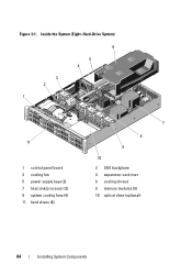
Inside the System (Eight-Hard-Drive System) 6 5 4 3 2 1 11 1 control panel board 3 cooling fan 5 power supply bays (2) 7 heat sink/processor (2) 9 system cooling fans (4) 11 hard drives (8) 7 8 9 10 2 SAS backplane 4 expansion-card riser 6 cooling shroud 8 memory modules (8) 10 optical drive (optional) 84 Installing System Components Figure 3-1.
Inside the System (Eight-Hard-Drive System) 6 5 4 3 2 1 11 1 control panel board 3 cooling fan 5 power supply bays (2) 7 heat sink/processor (2) 9 system cooling fans (4) 11 hard drives (8) 7 8 9 10 2 SAS backplane 4 expansion-card riser 6 cooling shroud 8 memory modules (8) 10 optical drive (optional) 84 Installing System Components Figure 3-1.
Hardware Owner's Manual
Page 85
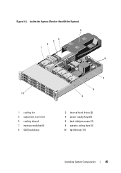
Figure 3-2. Inside the System (Twelve-Hard-Drive System) 5 4 3 2 1 6 10 1 cooling fan 3 expansion-card riser 5 cooling shroud 7 memory modules (8) 9 SAS backplane 7 8 9 2 internal hard drives (2) 4 power supply bays (2) 6 heat sink/processor (2) 8 system cooling fans (4) 10 hard drives (12) Installing System Components 85
Figure 3-2. Inside the System (Twelve-Hard-Drive System) 5 4 3 2 1 6 10 1 cooling fan 3 expansion-card riser 5 cooling shroud 7 memory modules (8) 9 SAS backplane 7 8 9 2 internal hard drives (2) 4 power supply bays (2) 6 heat sink/processor (2) 8 system cooling fans (4) 10 hard drives (12) Installing System Components 85
Hardware Owner's Manual
Page 90
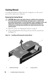
Read and follow the safety instructions that is not authorized by Dell is not covered by the online or telephone service and support team. Damage due to servicing that came with the product. 1 Open the system. See ..., or as directed by your warranty. See "Opening the System" on page 87. 2 Grasp and gently lift the shroud up and away from the cooling fans over the system processor(s) and memory module(s). Removing the Cooling Shroud CAUTION: Many repairs may only be done by a certified service technician. Installing and Removing...
Read and follow the safety instructions that is not authorized by Dell is not covered by the online or telephone service and support team. Damage due to servicing that came with the product. 1 Open the system. See ..., or as directed by your warranty. See "Opening the System" on page 87. 2 Grasp and gently lift the shroud up and away from the cooling fans over the system processor(s) and memory module(s). Removing the Cooling Shroud CAUTION: Many repairs may only be done by a certified service technician. Installing and Removing...
Hardware Owner's Manual
Page 91
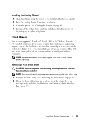
... drives are connected to four 3.5-inch SAS or SATA hard drives. See "Removing the Front Bezel" on page 86. 2 Grasp the front of the numbered fan bays as hotswappable.
... drives are connected to four 3.5-inch SAS or SATA hard drives. See "Removing the Front Bezel" on page 86. 2 Grasp the front of the numbered fan bays as hotswappable.
Hardware Owner's Manual
Page 105
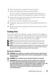
... modules. See "Closing the System" on your system configuration. See "Removing the Front Bezel" on the fan assembly. Read and follow the safety instructions that is not authorized by Dell is not supported. NOTE: Hot-swap removal or installation of the drive. CAUTION: Many repairs may only ...be done by the online or telephone service and support team. Cooling Fans Your system contains four cooling fans, single- These provide cooling for the fan to prevent ...
... modules. See "Closing the System" on your system configuration. See "Removing the Front Bezel" on the fan assembly. Read and follow the safety instructions that is not authorized by Dell is not supported. NOTE: Hot-swap removal or installation of the drive. CAUTION: Many repairs may only ...be done by the online or telephone service and support team. Cooling Fans Your system contains four cooling fans, single- These provide cooling for the fan to prevent ...
Hardware Owner's Manual
Page 106
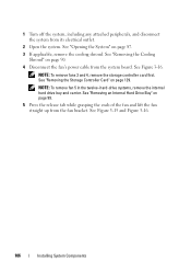
.... 106 Installing System Components See "Removing the Cooling Shroud" on page 99. 5 Press the release tab while grasping the ends of the fan and lift the fan straight up from the system board. See Figure 3-16. See "Removing an Internal Hard Drive Bay" on page 90. 4 Disconnect the... fan's power cable from the fan bracket. NOTE: To remove fan 5 in the twelve-hard-drive systems, remove the internal hard drive bay and carrier. 1 Turn off the system, including any...
.... 106 Installing System Components See "Removing the Cooling Shroud" on page 99. 5 Press the release tab while grasping the ends of the fan and lift the fan straight up from the system board. See Figure 3-16. See "Removing an Internal Hard Drive Bay" on page 90. 4 Disconnect the... fan's power cable from the fan bracket. NOTE: To remove fan 5 in the twelve-hard-drive systems, remove the internal hard drive bay and carrier. 1 Turn off the system, including any...
Hardware Owner's Manual
Page 107
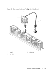
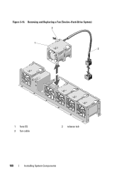
Figure 3-15. Removing and Replacing a Fan (Eight-Hard-Drive System) 2 1 3 1 fans (5) 3 fan cable 2 release tab Installing System Components 107
Figure 3-15. Removing and Replacing a Fan (Eight-Hard-Drive System) 2 1 3 1 fans (5) 3 fan cable 2 release tab Installing System Components 107
Hardware Owner's Manual
Page 108
Removing and Replacing a Fan (Twelve-Hard-Drive System) 2 1 3 1 fans (5) 3 fan cable 2 release tab 108 Installing System Components Figure 3-16.
Removing and Replacing a Fan (Twelve-Hard-Drive System) 2 1 3 1 fans (5) 3 fan cable 2 release tab 108 Installing System Components Figure 3-16.

Hardware Owner's Manual
Page 109
... so that the side with the power cable faces toward the back of the system. 2 Slide the fan module into the fan assembly until the fan is listed on the power supply label. See "Installing the Power Supply Blank" on page 91. 6 Close the system. See "Installing the Cooling Shroud...seated. If two power supplies are installed, the second power supply provides hot-swappable, power redundancy. See Figure 3-15 and Figure 3-16. 3 Connect the fan's power cable to the power connector on the system board. 4 Route the power cable through the guides on page 101. 5 Replace the cooling shroud. ...
... so that the side with the power cable faces toward the back of the system. 2 Slide the fan module into the fan assembly until the fan is listed on the power supply label. See "Installing the Power Supply Blank" on page 91. 6 Close the system. See "Installing the Cooling Shroud...seated. If two power supplies are installed, the second power supply provides hot-swappable, power redundancy. See Figure 3-15 and Figure 3-16. 3 Connect the fan's power cable to the power connector on the system board. 4 Route the power cable through the guides on page 101. 5 Replace the cooling shroud. ...
Hardware Owner's Manual
Page 161
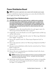
...the front of the system. 3 Remove the power supplies from the system board (see "System Board" on your system directly behind the power supply fan module. See "Removing a Redundant Power Supply" on page 126. 5 Remove the expansion card riser. See "Removing an Expansion Card" on page ...110. 4 Remove the expansion cards. The power distribution board is not covered by Dell is located on page 165). 7 Disconnect the fan cable. 8 Remove the screws securing the power distribution board to the chassis. See Figure 3-37. See "Removing an ...
...the front of the system. 3 Remove the power supplies from the system board (see "System Board" on your system directly behind the power supply fan module. See "Removing a Redundant Power Supply" on page 126. 5 Remove the expansion card riser. See "Removing an Expansion Card" on page ...110. 4 Remove the expansion cards. The power distribution board is not covered by Dell is located on page 165). 7 Disconnect the fan cable. 8 Remove the screws securing the power distribution board to the chassis. See Figure 3-37. See "Removing an ...
Hardware Owner's Manual
Page 162
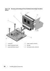
Removing and Installing the Power Distribution Board (Eight-Hard-Drive System) 3 4 2 1 6 1 screws (4) 3 power-interposer board 5 power-distribution board 5 2 power supply connector 4 blue tab 6 fan module cable connector 162 Installing System Components Figure 3-36.
Removing and Installing the Power Distribution Board (Eight-Hard-Drive System) 3 4 2 1 6 1 screws (4) 3 power-interposer board 5 power-distribution board 5 2 power supply connector 4 blue tab 6 fan module cable connector 162 Installing System Components Figure 3-36.


