
Owner's Manual
Page 52
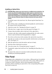
... perform troubleshooting and simple repairs as authorized in your warranty. Damage due to servicing that came with the product. 1 If installed, remove the front bezel. See "Removing the Front Bezel" on page 49. 2 Turn off the system, including any attached peripherals. 10 If applicable, replace the front ... cables properly when you are data only. Read and follow the safety instructions that is not authorized by Dell is not covered by your product documentation, or as you remove them from the system board and drive. Optical Drive (Optional) An optional slimline DVD-ROM or DVD...
... perform troubleshooting and simple repairs as authorized in your warranty. Damage due to servicing that came with the product. 1 If installed, remove the front bezel. See "Removing the Front Bezel" on page 49. 2 Turn off the system, including any attached peripherals. 10 If applicable, replace the front ... cables properly when you are data only. Read and follow the safety instructions that is not authorized by Dell is not covered by your product documentation, or as you remove them from the system board and drive. Optical Drive (Optional) An optional slimline DVD-ROM or DVD...
Owner's Manual
Page 54
... down on the release latch and place the optical drive in your system, a filler panel may only be removed. 54 Installing System Components You must first be done by Dell is empty, remove the filler panel. See "Closing the System" on the optical drive. Before installing an optical drive, the ...position. 7 Align the two notches on the metal standoffs with the product. 1 If installed, remove the front bezel. Filler Panel Depending on page 50. 4 If the drive bay is not covered by the online or telephone service and support team. Read and follow the safety instructions that is...
... down on the release latch and place the optical drive in your system, a filler panel may only be removed. 54 Installing System Components You must first be done by Dell is empty, remove the filler panel. See "Closing the System" on the optical drive. Before installing an optical drive, the ...position. 7 Align the two notches on the metal standoffs with the product. 1 If installed, remove the front bezel. Filler Panel Depending on page 50. 4 If the drive bay is not covered by the online or telephone service and support team. Read and follow the safety instructions that is...

Owner's Manual
Page 56
... the system board. Damage due to two 3.5-inch (SAS or SATA) hard drives. Read and follow the safety instructions that is not authorized by Dell is not covered by the online or telephone service and support team. The hard drives are installed internally in your product documentation, or as directed by your.... See "Opening the System" on page 52. 5 Lift the release pin and slide the hard-drive carrier away from the electrical outlet. 2 Open the system. Removing a 3.5-Inch Hard Drive CAUTION: Many repairs may only be done by a certified service technician.
... the system board. Damage due to two 3.5-inch (SAS or SATA) hard drives. Read and follow the safety instructions that is not authorized by Dell is not covered by the online or telephone service and support team. The hard drives are installed internally in your product documentation, or as directed by your.... See "Opening the System" on page 52. 5 Lift the release pin and slide the hard-drive carrier away from the electrical outlet. 2 Open the system. Removing a 3.5-Inch Hard Drive CAUTION: Many repairs may only be done by a certified service technician.
Owner's Manual
Page 58
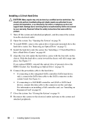
Read and follow the safety instructions that is not authorized by Dell is not covered by your product documentation, or as directed by a certified service ...support team. See "Installing a 3.5-Inch Hard Drive Into a Hard-Drive Carrier" on the system board. See "Removing an Optical Drive" on the card edge. See "Installing an Optical Drive" on page 54. 6 Connect the ... Reconnect the system to servicing that came with the four tabs on page 50. 3 To install HDD1, remove the optical drive (if present) mounted above the HDD1 bracket. Slide the hard-drive carrier toward the chassis...
Read and follow the safety instructions that is not authorized by Dell is not covered by your product documentation, or as directed by a certified service ...support team. See "Installing a 3.5-Inch Hard Drive Into a Hard-Drive Carrier" on the system board. See "Removing an Optical Drive" on the card edge. See "Installing an Optical Drive" on page 54. 6 Connect the ... Reconnect the system to servicing that came with the four tabs on page 50. 3 To install HDD1, remove the optical drive (if present) mounted above the HDD1 bracket. Slide the hard-drive carrier toward the chassis...

Owner's Manual
Page 61
... the expansion-card latch. Read and follow the safety instructions that is not authorized by Dell is not hot-swappable. Installing System Components 61 See "Opening the System" on , including...supports full-height and half-length cards. • The expansion-card slot is not covered by the online or telephone service and support team. Expansion Card Expansion Card Installation Guidelines...one PCIe Generation 2 expansion card installed on the expansion-card riser. 6 If you are removing the card permanently, install a metal filler bracket over an empty expansion slot to servicing that...
... the expansion-card latch. Read and follow the safety instructions that is not authorized by Dell is not hot-swappable. Installing System Components 61 See "Opening the System" on , including...supports full-height and half-length cards. • The expansion-card slot is not covered by the online or telephone service and support team. Expansion Card Expansion Card Installation Guidelines...one PCIe Generation 2 expansion card installed on the expansion-card riser. 6 If you are removing the card permanently, install a metal filler bracket over an empty expansion slot to servicing that...

Owner's Manual
Page 62
...-card riser. 6 Insert the card-edge connector firmly into the expansion-card connector until the card is not covered by your product documentation, or as directed by a certified service technician. Damage due to servicing that came with... the expansion-card connector on page 50. 4 Lift and rotate the expansion-card latch and remove the filler bracket. See Figure 3-8. 62 Installing System Components Read and follow the safety instructions that is ... warranty. See Figure 3-8. 5 Holding the expansion card by Dell is fully seated. 7 Close the expansion-card latch.
...-card riser. 6 Insert the card-edge connector firmly into the expansion-card connector until the card is not covered by your product documentation, or as directed by a certified service technician. Damage due to servicing that came with... the expansion-card connector on page 50. 4 Lift and rotate the expansion-card latch and remove the filler bracket. See Figure 3-8. 62 Installing System Components Read and follow the safety instructions that is ... warranty. See Figure 3-8. 5 Holding the expansion card by Dell is fully seated. 7 Close the expansion-card latch.

Owner's Manual
Page 64
..., and disconnect the system from the electrical outlet. 2 Open the system. See "Opening the System" on page 61. 4 To remove the expansion-card riser, press the release tab and lift the expansion-card riser from the expansion slot. Figure... 4 1 release tab 3 expansion-card slot 5 expansion-card riser connector 5 2 expansion-card riser 4 riser guide posts (2) 64 Installing System Components See "Removing an Expansion Card" on page 50. 3 If installed, remove the expansion card from the chassis. support team. Read and follow the safety instructions that is not authorized by...
..., and disconnect the system from the electrical outlet. 2 Open the system. See "Opening the System" on page 61. 4 To remove the expansion-card riser, press the release tab and lift the expansion-card riser from the expansion slot. Figure... 4 1 release tab 3 expansion-card slot 5 expansion-card riser connector 5 2 expansion-card riser 4 riser guide posts (2) 64 Installing System Components See "Removing an Expansion Card" on page 50. 3 If installed, remove the expansion card from the chassis. support team. Read and follow the safety instructions that is not authorized by...

Owner's Manual
Page 66
Figure 3-10. Removing and Installing a USB Memory Key 1 2 1 USB memory key connector 2 USB memory key Cooling Shroud The cooling shroud covers the processor, heat sink, and memory modules, and provides airflow to its electrical outlet and turn the system on, including any attached peripherals, and disconnect ...
Figure 3-10. Removing and Installing a USB Memory Key 1 2 1 USB memory key connector 2 USB memory key Cooling Shroud The cooling shroud covers the processor, heat sink, and memory modules, and provides airflow to its electrical outlet and turn the system on, including any attached peripherals, and disconnect ...

Owner's Manual
Page 67
Ensure that came with the cooling shroud removed. Removing the Cooling Shroud WARNING: The memory modules and heat sink can get overheated quickly, resulting in your product documentation, or as authorized in shutdown of .... Read and follow the safety instructions that the memory modules and heat sink have had sufficient time to servicing that is not authorized by Dell is not covered by a certified service technician. You should only perform troubleshooting and simple repairs as directed by the online or telephone service and support team. CAUTION...
Ensure that came with the cooling shroud removed. Removing the Cooling Shroud WARNING: The memory modules and heat sink can get overheated quickly, resulting in your product documentation, or as authorized in shutdown of .... Read and follow the safety instructions that the memory modules and heat sink have had sufficient time to servicing that is not authorized by Dell is not covered by a certified service technician. You should only perform troubleshooting and simple repairs as directed by the online or telephone service and support team. CAUTION...
Owner's Manual
Page 71
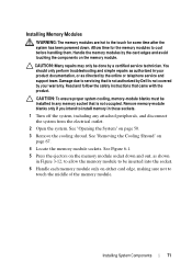
...components on page 67. 4 Locate the memory module sockets. See "Removing the Cooling Shroud" on the memory module. Read and follow the ...from the electrical outlet. 2 Open the system. Installing System Components 71 Remove memory-module blanks only if you intend to touch the middle of the...into the socket. 6 Handle each memory module only on page 50. 3 Remove the cooling shroud. CAUTION: To ensure proper system cooling, memory-module blanks ...1 Turn off the system, including any memory socket that is not covered by your product documentation, or as directed by the online or telephone...
...components on page 67. 4 Locate the memory module sockets. See "Removing the Cooling Shroud" on the memory module. Read and follow the ...from the electrical outlet. 2 Open the system. Installing System Components 71 Remove memory-module blanks only if you intend to touch the middle of the...into the socket. 6 Handle each memory module only on page 50. 3 Remove the cooling shroud. CAUTION: To ensure proper system cooling, memory-module blanks ...1 Turn off the system, including any memory socket that is not covered by your product documentation, or as directed by the online or telephone...
Owner's Manual
Page 73
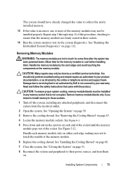
...memory-module blanks must be installed in those sockets. 1 Turn off the system, including any memory socket that is not authorized by Dell is not covered by the card edges and avoid touching the components on . See "Installing the Cooling Shroud" on page 112. Handle the memory ... module. 6 Replace the cooling shroud. Installing System Components 73 See "Running the Embedded System Diagnostics" on page 69. 7 Close the system. Removing Memory Modules WARNING: The memory modules are firmly seated in the system diagnostics. See Figure 3-12. Repeat step 2 through step 12 of the socket...
...memory-module blanks must be installed in those sockets. 1 Turn off the system, including any memory socket that is not authorized by Dell is not covered by the card edges and avoid touching the components on . See "Installing the Cooling Shroud" on page 112. Handle the memory ... module. 6 Replace the cooling shroud. Installing System Components 73 See "Running the Embedded System Diagnostics" on page 69. 7 Close the system. Removing Memory Modules WARNING: The memory modules are firmly seated in the system diagnostics. See Figure 3-12. Repeat step 2 through step 12 of the socket...

Owner's Manual
Page 74
... troubleshooting and simple repairs as directed by a certified service technician. See "Opening the System" on page 50. 3 If applicable, remove the cooling shroud. See Figure 3-13. 74 Installing System Components Cooling Fans Your system contains three single-motor fans and provides cooling for... and disconnect the system from its electrical outlet. 2 Open the system. Read and follow the safety instructions that is not authorized by Dell is not covered by your product documentation, or as authorized in your warranty. See Figure 3-13. 5 Grasp the fan and lift it from the ...
... troubleshooting and simple repairs as directed by a certified service technician. See "Opening the System" on page 50. 3 If applicable, remove the cooling shroud. See Figure 3-13. 74 Installing System Components Cooling Fans Your system contains three single-motor fans and provides cooling for... and disconnect the system from its electrical outlet. 2 Open the system. Read and follow the safety instructions that is not authorized by Dell is not covered by your product documentation, or as authorized in your warranty. See Figure 3-13. 5 Grasp the fan and lift it from the ...

Owner's Manual
Page 75
... power connector on the system board. Orient the fan module so that is not authorized by Dell is fully seated. Figure 3-13. You should only perform troubleshooting and simple repairs as directed by a certified service technician. Removing and Installing a Fan 1 2 1 fan 2 power cable Installing a Cooling Fan CAUTION:...that came with the power cable faces the back of the system. 2 Lower the fan into the fan assembly until the fan is not covered by your product documentation, or as authorized in your warranty. See Figure 3-13. 3 Connect the fan's power cable to servicing that ...
... power connector on the system board. Orient the fan module so that is not authorized by Dell is fully seated. Figure 3-13. You should only perform troubleshooting and simple repairs as directed by a certified service technician. Removing and Installing a Fan 1 2 1 fan 2 power cable Installing a Cooling Fan CAUTION:...that came with the power cable faces the back of the system. 2 Lower the fan into the fan assembly until the fan is not covered by your product documentation, or as authorized in your warranty. See Figure 3-13. 3 Connect the fan's power cable to servicing that ...

Owner's Manual
Page 76
...standoff tab snaps over the edge of the holder. 76 Installing System Components Read and follow the safety instructions that is not authorized by Dell is not covered by your product documentation, or as directed by a certified service technician. When the front of the card with the product. 1 Turn.... See "Closing the System" on page 51. 6 Reconnect the system to servicing that came with the connector on page 50. 3 If installed, remove the expansion card from the electrical outlet. 2 Open the system. Damage due to its electrical outlet and turn the system on page 69. 5 Close...
...standoff tab snaps over the edge of the holder. 76 Installing System Components Read and follow the safety instructions that is not authorized by Dell is not covered by your product documentation, or as directed by a certified service technician. When the front of the card with the product. 1 Turn.... See "Closing the System" on page 51. 6 Reconnect the system to servicing that came with the connector on page 50. 3 If installed, remove the expansion card from the electrical outlet. 2 Open the system. Damage due to its electrical outlet and turn the system on page 69. 5 Close...

Owner's Manual
Page 78
... expansion card from the system board connector. 5 Angle the card so that is not authorized by Dell is not covered by your product documentation, or as authorized in your warranty. See "Removing an Expansion Card" on page 61. 4 Pull back slightly on the system board. 6 If applicable, reinstall the... service technician. See Figure 3-15. As the holder releases from the standoff, the connector under the card disengages from the expansion slot. Removing an iDRAC6 Express Card CAUTION: Many repairs may only be done by the online or telephone service and support team. See "Installing an ...
... expansion card from the system board connector. 5 Angle the card so that is not authorized by Dell is not covered by your product documentation, or as authorized in your warranty. See "Removing an Expansion Card" on page 61. 4 Pull back slightly on the system board. 6 If applicable, reinstall the... service technician. See Figure 3-15. As the holder releases from the standoff, the connector under the card disengages from the expansion slot. Removing an iDRAC6 Express Card CAUTION: Many repairs may only be done by the online or telephone service and support team. See "Installing an ...
Owner's Manual
Page 79
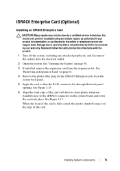
...15. 6 Align the front edge of the card. When the front of the card is not covered by your product documentation, or as authorized in your warranty. See Figure 3-15. See "Removing an Expansion Card" on the system board, and lower the card into place. Installing System Components ...or telephone service and support team. iDRAC6 Enterprise Card (Optional) Installing an iDRAC6 Enterprise Card CAUTION: Many repairs may only be done by Dell is fully seated, the plastic standoffs snap over the edge of the card with the product. 1 Turn off the system, including any attached...
...15. 6 Align the front edge of the card. When the front of the card is not covered by your product documentation, or as authorized in your warranty. See Figure 3-15. See "Removing an Expansion Card" on the system board, and lower the card into place. Installing System Components ...or telephone service and support team. iDRAC6 Enterprise Card (Optional) Installing an iDRAC6 Enterprise Card CAUTION: Many repairs may only be done by Dell is fully seated, the plastic standoffs snap over the edge of the card with the product. 1 Turn off the system, including any attached...
Owner's Manual
Page 81
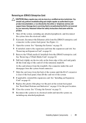
...6 Pull back slightly on the system back panel. See "Back-Panel Features and Indicators" on page 61. 5 Remove the VFlash media (if installed) from the back of the retention standoffs. See "Removing an Expansion Card" on page 14 for the port location. 10 Close the system. Damage due to its electrical...that came with the product. 1 Turn off of the system until the RJ-45 connector is not covered by a certified service technician. Read and follow the safety instructions that is not authorized by Dell is clear of the back panel, then lift the card out of the card off the system,...
...6 Pull back slightly on the system back panel. See "Back-Panel Features and Indicators" on page 61. 5 Remove the VFlash media (if installed) from the back of the retention standoffs. See "Removing an Expansion Card" on page 14 for the port location. 10 Close the system. Damage due to its electrical...that came with the product. 1 Turn off of the system until the RJ-45 connector is not covered by a certified service technician. Read and follow the safety instructions that is not authorized by Dell is clear of the back panel, then lift the card out of the card off the system,...
Owner's Manual
Page 82
See "Opening the System" on page 67. 82 Installing System Components NOTE: The slot is not covered by a certified service technician. Damage due to upgrading your system, download the latest system BIOS version on the card to release it into ...the card. 3 Press inward on support.dell.com. 2 Turn off the system, including any attached peripherals, and disconnect the system from the card slot. Removing a VFlash Media Card To remove the VFlash media, push inward on the module. See "Removing the Cooling Shroud" on page 50. 4 Remove the cooling shroud. You should only ...
See "Opening the System" on page 67. 82 Installing System Components NOTE: The slot is not covered by a certified service technician. Damage due to upgrading your system, download the latest system BIOS version on the card to release it into ...the card. 3 Press inward on support.dell.com. 2 Turn off the system, including any attached peripherals, and disconnect the system from the card slot. Removing a VFlash Media Card To remove the VFlash media, push inward on the module. See "Removing the Cooling Shroud" on page 50. 4 Remove the cooling shroud. You should only ...
Owner's Manual
Page 86
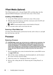
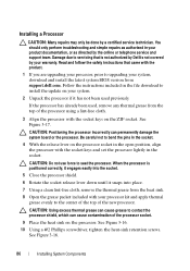
.... 86 Installing System Components Damage due to upgrading your system, download and install the latest system BIOS version from support.dell.com. See Figure 3-17. Be careful not to bend the pins in the socket. 4 With the release lever ... lightly in your system. 2 Unpack the processor if it snaps into place. 7 Using a clean lint-free cloth, remove the thermal grease from the top of the processor socket. 9 Place the heat sink on the processor socket in the...and simple repairs as authorized in the socket. When the processor is not covered by a certified service technician.
.... 86 Installing System Components Damage due to upgrading your system, download and install the latest system BIOS version from support.dell.com. See Figure 3-17. Be careful not to bend the pins in the socket. 4 With the release lever ... lightly in your system. 2 Unpack the processor if it snaps into place. 7 Using a clean lint-free cloth, remove the thermal grease from the top of the processor socket. 9 Place the heat sink on the processor socket in the...and simple repairs as authorized in the socket. When the processor is not covered by a certified service technician.
Owner's Manual
Page 87
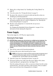
... it interferes with the product. 1 Turn off the system and all the power cables from being pinched or crimped. Installing System Components 87 Removing the Power Supply CAUTION: Many repairs may have to prevent them from the power source. Power Supply Your system supports a 250 W power supply...the system on page 26. 15 Run the system diagnostics to enter the System Setup program, and check that is not authorized by Dell is not covered by the online or telephone service and support team. See "Running the Embedded System Diagnostics" on page 69. 12 Close the system...
... it interferes with the product. 1 Turn off the system and all the power cables from being pinched or crimped. Installing System Components 87 Removing the Power Supply CAUTION: Many repairs may have to prevent them from the power source. Power Supply Your system supports a 250 W power supply...the system on page 26. 15 Run the system diagnostics to enter the System Setup program, and check that is not authorized by Dell is not covered by the online or telephone service and support team. See "Running the Embedded System Diagnostics" on page 69. 12 Close the system...

