User Manual
Page 1
...5.5(x32) • Red Hat Enterprise Linux 5.5(x64) • SUSE Linux Enterprise Server 10 SP3 (x64) March 2011 Information Update Dell Systems Build and Update Utility The following drivers are displayed but not supported by the Systems Build Update Utility (SBUU): • Red...not available in SBUU: • Video driver for Microsoft Windows Server 2008 R2 (x64) • Broadcom Ethernet driver for all supported operating systems • Intel driver for Microsoft Windows Small Business Server 2011 To download the latest drivers, go to support.dell.com. Dell PowerEdge R210 II Systems-
...5.5(x32) • Red Hat Enterprise Linux 5.5(x64) • SUSE Linux Enterprise Server 10 SP3 (x64) March 2011 Information Update Dell Systems Build and Update Utility The following drivers are displayed but not supported by the Systems Build Update Utility (SBUU): • Red...not available in SBUU: • Video driver for Microsoft Windows Server 2008 R2 (x64) • Broadcom Ethernet driver for all supported operating systems • Intel driver for Microsoft Windows Small Business Server 2011 To download the latest drivers, go to support.dell.com. Dell PowerEdge R210 II Systems-

Getting Started Guide
Page 12
..., DTE, 16550-compatible Two 4-pin, USB 2.0-compliant 15-pin VGA One 7-pin connector 15-pin VGA Two 4-pin, USB 2.0-compliant Two 4-pin, USB 2.0-compliant Video Video type Video memory Matrox G200, integrated in Winbond WPCM450 8 MB Power AC power supply (per power supply) Wattage 250 W Voltage 100 VAC-240 VAC, 50 Hz/60...
..., DTE, 16550-compatible Two 4-pin, USB 2.0-compliant 15-pin VGA One 7-pin connector 15-pin VGA Two 4-pin, USB 2.0-compliant Two 4-pin, USB 2.0-compliant Video Video type Video memory Matrox G200, integrated in Winbond WPCM450 8 MB Power AC power supply (per power supply) Wattage 250 W Voltage 100 VAC-240 VAC, 50 Hz/60...
Owner's Manual
Page 7
... Board 95 4 Troubleshooting Your System 97 Safety First-For You and Your System 97 Troubleshooting System Startup Failure 97 Troubleshooting External Connections 97 Troubleshooting the Video Subsystem 98 Troubleshooting a USB Device 98 Troubleshooting a Serial I/O Device 99 Troubleshooting a NIC 99 Troubleshooting a Wet System 100 Troubleshooting a Damaged System 101 Troubleshooting the System Battery...
... Board 95 4 Troubleshooting Your System 97 Safety First-For You and Your System 97 Troubleshooting System Startup Failure 97 Troubleshooting External Connections 97 Troubleshooting the Video Subsystem 98 Troubleshooting a USB Device 98 Troubleshooting a Serial I/O Device 99 Troubleshooting a NIC 99 Troubleshooting a Wet System 100 Troubleshooting a Damaged System 101 Troubleshooting the System Battery...
Owner's Manual
Page 12
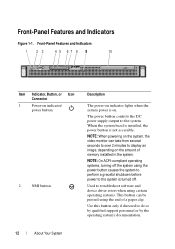
... button Description The power-on indicator lights when the system power is on the amount of a paper clip. NOTE: When powering on the system, the video monitor can be pressed using the power button causes the system to perform a graceful shutdown before power to display an image, depending on . Used to...
... button Description The power-on indicator lights when the system power is on the amount of a paper clip. NOTE: When powering on the system, the video monitor can be pressed using the power button causes the system to perform a graceful shutdown before power to display an image, depending on . Used to...
Owner's Manual
Page 13
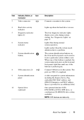
... hard drive is pushed again. Space is pushed, the system status indicators on page 17. About Your System 13 Item Indicator, Button, or Icon Connector 3 Video connector 4 Hard-drive activity indicator 5 Diagnostic indicator lights (4) 6 System status indicator 7 System identification button 8 USB connectors (2) 9 System identification panel 10 Optical drive (optional) Description Connects...
... hard drive is pushed again. Space is pushed, the system status indicators on page 17. About Your System 13 Item Indicator, Button, or Icon Connector 3 Video connector 4 Hard-drive activity indicator 5 Diagnostic indicator lights (4) 6 System status indicator 7 System identification button 8 USB connectors (2) 9 System identification panel 10 Optical drive (optional) Description Connects...

Owner's Manual
Page 14
... Indicators 1 2 3 4 5 6 7 8 9 10 11 12 13 Item Indicator, Button, or Icon Connector 1 iDRAC6 Enterprise port (optional) 2 VFlash media slot (optional) 3 PCIe expansion card slot 4 Serial connector 5 Video connector 6 eSATA 7 USB connectors (2) 8 Ethernet connectors (2) Description Dedicated management port for the optional iDRAC6 Enterprise card. The ports are USB 2.0-compliant. Back-Panel Features and...
... Indicators 1 2 3 4 5 6 7 8 9 10 11 12 13 Item Indicator, Button, or Icon Connector 1 iDRAC6 Enterprise port (optional) 2 VFlash media slot (optional) 3 PCIe expansion card slot 4 Serial connector 5 Video connector 6 eSATA 7 USB connectors (2) 8 Ethernet connectors (2) Description Dedicated management port for the optional iDRAC6 Enterprise card. The ports are USB 2.0-compliant. Back-Panel Features and...

Owner's Manual
Page 17
... and press the pre-BIOS failure has power button. See "Troubleshooting the Processor" on the system front panel display error codes during system startup. Possible video failure. About Your System 17
... and press the pre-BIOS failure has power button. See "Troubleshooting the Processor" on the system front panel display error codes during system startup. Possible video failure. About Your System 17
Owner's Manual
Page 29
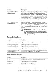
... does not affect the operation of system memory. The user can press to continue or to the system. Displays the type of video memory. Options are Enabled and Disabled. Processor Settings Screen Option 64-bit Core Speed Bus Speed Description Specifies if the processor supports ... system does not halt if an error occurs during POST. Memory Settings Screen Option System Memory Size System Memory Type System Memory Speed Video Memory System Memory Testing (Enabled default) Description Displays the amount of the keyboard itself if a keyboard is attached to enter the System...
... does not affect the operation of system memory. The user can press to continue or to the system. Displays the type of video memory. Options are Enabled and Disabled. Processor Settings Screen Option 64-bit Core Speed Bus Speed Description Specifies if the processor supports ... system does not halt if an error occurs during POST. Memory Settings Screen Option System Memory Size System Memory Type System Memory Speed Video Memory System Memory Testing (Enabled default) Description Displays the amount of the keyboard itself if a keyboard is attached to enter the System...
Owner's Manual
Page 32
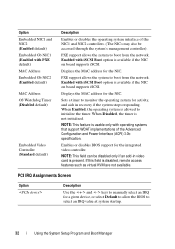
...the NIC on board supports iSCSI. NOTE: This field can be accessed through the system's management controller). Displays the MAC address for the integrated video controller. PXE support allows the system to boot from the network. Enables or disables BIOS support for the NIC. When Disabled, the timer ... KVM are not available. If this field is not initialized. Sets a timer to monitor the operating system for activity, and aids in video card is allowed to manually select an IRQ for the NIC. PCI IRQ Assignments Screen Option Description Use the and keys to initialize the ...
...the NIC on board supports iSCSI. NOTE: This field can be accessed through the system's management controller). Displays the MAC address for the integrated video controller. PXE support allows the system to boot from the network. Enables or disables BIOS support for the NIC. When Disabled, the timer ... KVM are not available. If this field is not initialized. Sets a timer to monitor the operating system for activity, and aids in video card is allowed to manually select an IRQ for the NIC. PCI IRQ Assignments Screen Option Description Use the and keys to initialize the ...
Owner's Manual
Page 69
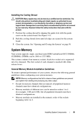
...8226; Memory modules are secured to 4. NOTE: Memory configurations that fail to servicing that came with the product. 1 Position the cooling shroud by Dell is organized into two channels. See "Opening and Closing the System" on the system board. See Figure 3-11. 2 Push the cooling shroud ... the online or telephone service and support team. Damage due to observe these guidelines can prevent your system from starting and producing any video output. • Except for memory channels that are unused, all edges are installed in your system memory. Installing System Components 69 ...
...8226; Memory modules are secured to 4. NOTE: Memory configurations that fail to servicing that came with the product. 1 Position the cooling shroud by Dell is organized into two channels. See "Opening and Closing the System" on the system board. See Figure 3-11. 2 Push the cooling shroud ... the online or telephone service and support team. Damage due to observe these guidelines can prevent your system from starting and producing any video output. • Except for memory channels that are unused, all edges are installed in your system memory. Installing System Components 69 ...

Owner's Manual
Page 97
Troubleshooting Your System 97 The reverse is not covered by Dell is also true. You must boot to the BIOS boot ...For all external cables are securely attached to servicing that is not authorized by your system before troubleshooting any video output. See "System Messages" on page 19 for the front-panel and back-panel connectors on page... "System Memory" on your warranty. Troubleshooting System Startup Failure If your system halts during startup prior to video output, especially after installing an operating system from the Boot Manager, the system will hang. See "Using...
Troubleshooting Your System 97 The reverse is not covered by Dell is also true. You must boot to the BIOS boot ...For all external cables are securely attached to servicing that is not authorized by your system before troubleshooting any video output. See "System Messages" on page 19 for the front-panel and back-panel connectors on page... "System Memory" on your warranty. Troubleshooting System Startup Failure If your system halts during startup prior to video output, especially after installing an operating system from the Boot Manager, the system will hang. See "Using...
Owner's Manual
Page 98
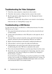
... 1 Check the system and power connections to the monitor. 2 Check the video interface cabling from the system to troubleshoot a USB keyboard /mouse. If the tests fail, see "Disabling a Forgotten Password" on page 118 for instructions on setting ... the appropriate online diagnostic test. For other USB devices attached to the default settings. 98 Troubleshooting Your System If the system is not related to video hardware. If the tests run successfully, the problem is not accessible, see "Getting Help" on the opposite side of the system. 3 If the problem is...
... 1 Check the system and power connections to the monitor. 2 Check the video interface cabling from the system to troubleshoot a USB keyboard /mouse. If the tests fail, see "Disabling a Forgotten Password" on page 118 for instructions on setting ... the appropriate online diagnostic test. For other USB devices attached to the default settings. 98 Troubleshooting Your System If the system is not related to video hardware. If the tests run successfully, the problem is not accessible, see "Getting Help" on the opposite side of the system. 3 If the problem is...
Owner's Manual
Page 104
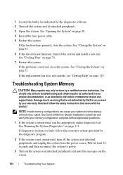
... can cause your memory configuration complies with the product. Wait at least 10 seconds and then reconnect the system to halt at startup without video output. If the fan functions properly, close the system. If the problem is operational, run the appropriate online diagnostic test. Read and ... as directed by the diagnostic software. 2 Turn off the system and install a new fan. Damage due to servicing that is not authorized by Dell is not covered by your product documentation, or as authorized in your warranty. See "Opening the System" on page 111. See "Running the ...
... can cause your memory configuration complies with the product. Wait at least 10 seconds and then reconnect the system to halt at startup without video output. If the fan functions properly, close the system. If the problem is operational, run the appropriate online diagnostic test. Read and ... as directed by the diagnostic software. 2 Turn off the system and install a new fan. Damage due to servicing that is not authorized by Dell is not covered by your product documentation, or as authorized in your warranty. See "Opening the System" on page 111. See "Running the ...
Owner's Manual
Page 124
..., 109 external connections, 97 hard drive, 108 internal USB key, 106 keyboard, 98 memory, 104 NIC, 99 power supply, 103 processor, 110 system cooling, 103 video, 98 wet system, 100 U UEFI Boot Manager entering, 37 main screen, 38 System Utilities screen, 39 UEFI Boot Manager Screen, 38 upgrades processor, 82 USB...
..., 109 external connections, 97 hard drive, 108 internal USB key, 106 keyboard, 98 memory, 104 NIC, 99 power supply, 103 processor, 110 system cooling, 103 video, 98 wet system, 100 U UEFI Boot Manager entering, 37 main screen, 38 System Utilities screen, 39 UEFI Boot Manager Screen, 38 upgrades processor, 82 USB...


