
EMC Installation and Service Manual
Page 3
Contents Chapter 1: Dell EMC PowerEdge C4140 system overview 7 Front view and panel of the system...7 Control panel...8 Rear view of the system ...9 NIC indicator codes...9 Power supply unit indicator ...10 Inside the system...11 System information label...14 Chapter 2: Documentation resources 20 Chapter 3: Technical specifications 22 Chassis dimensions...23 System weight...23 GPU specifications...23 Processor specifications...24 Supported operating systems...24 PSU specifications...24 Cooling fans specifications...24 System battery specifications...25 Expansion bus specifications...25 Memory...
Contents Chapter 1: Dell EMC PowerEdge C4140 system overview 7 Front view and panel of the system...7 Control panel...8 Rear view of the system ...9 NIC indicator codes...9 Power supply unit indicator ...10 Inside the system...11 System information label...14 Chapter 2: Documentation resources 20 Chapter 3: Technical specifications 22 Chassis dimensions...23 System weight...23 GPU specifications...23 Processor specifications...24 Supported operating systems...24 PSU specifications...24 Cooling fans specifications...24 System battery specifications...25 Expansion bus specifications...25 Memory...

EMC Installation and Service Manual
Page 5
... key...97 Replacing the optional internal USB memory key...97 Graphics processing unit...98 PCIe Graphics processing unit...98 GPU installation guidelines...98 Removing a GPU riser cable from the GPU switch board 98 Removing a GPU...99 Removing a GPU riser cable board...101 Removing the GPU brackets from the GPUs removed from your system 102 Removing the...
... key...97 Replacing the optional internal USB memory key...97 Graphics processing unit...98 PCIe Graphics processing unit...98 GPU installation guidelines...98 Removing a GPU riser cable from the GPU switch board 98 Removing a GPU...99 Removing a GPU riser cable board...101 Removing the GPU brackets from the GPUs removed from your system 102 Removing the...
EMC Installation and Service Manual
Page 7
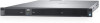
... power supply units (PSUs) • Optional two 2.5-inch cabled SATA SSDs installed only in PSU 2 bay Table 1. Control panel Dell EMC PowerEdge C4140 system overview 7 Topics: • Front view and panel of the system • Rear view of the system • Locating ... 1. Front view of the system (*)Optional Add-In Cards (2) x16 AIC PCIe (2) x16 AIC PCIe (2) x16 AIC PCIe (2) x16 AIC PCIe (2) x16 AIC PCIe Figure 1. GPU PCIe Link(s) (1) x16 Link Configuration C 2 4 (x16 Slot) PCIe (4) x16 Links Configuration G 2 4 (x16 Slot) PCIe (2) x16 Links Configuration K 2 4 (x16...
... power supply units (PSUs) • Optional two 2.5-inch cabled SATA SSDs installed only in PSU 2 bay Table 1. Control panel Dell EMC PowerEdge C4140 system overview 7 Topics: • Front view and panel of the system • Rear view of the system • Locating ... 1. Front view of the system (*)Optional Add-In Cards (2) x16 AIC PCIe (2) x16 AIC PCIe (2) x16 AIC PCIe (2) x16 AIC PCIe (2) x16 AIC PCIe Figure 1. GPU PCIe Link(s) (1) x16 Link Configuration C 2 4 (x16 Slot) PCIe (4) x16 Links Configuration G 2 4 (x16 Slot) PCIe (2) x16 Links Configuration K 2 4 (x16...

EMC Installation and Service Manual
Page 11
... 5. iDRAC MAC address and iDRAC secure password label Inside the system The 2.5-inch drive cage is completely independent of the GPU configuration of your system 1. The optional two 2.5-inch cabled SATA SSDs is supported on the switchboard, NVLink, or cabled...NDC) 11. Service Tag 2. Information tag (back view) 4. Figure 7. PCIe GPU (4) 3. Processor and heat sink (2) 7. Configuration B 1. PCIe switch board 4. Riser 1A (Low-profile PCIe expansion cards: Slots 1 and 2) Dell EMC PowerEdge C4140 system overview 11 Figure 6. Cooling fan (8) 5. Information tag 9. Locating Service Tag ...
... 5. iDRAC MAC address and iDRAC secure password label Inside the system The 2.5-inch drive cage is completely independent of the GPU configuration of your system 1. The optional two 2.5-inch cabled SATA SSDs is supported on the switchboard, NVLink, or cabled...NDC) 11. Service Tag 2. Information tag (back view) 4. Figure 7. PCIe GPU (4) 3. Processor and heat sink (2) 7. Configuration B 1. PCIe switch board 4. Riser 1A (Low-profile PCIe expansion cards: Slots 1 and 2) Dell EMC PowerEdge C4140 system overview 11 Figure 6. Cooling fan (8) 5. Information tag 9. Locating Service Tag ...

EMC Installation and Service Manual
Page 12
Processor and heat sink (2) 7. Riser 2A (Low-profile PCIe expansion card: Slot 3) 10. Figure 8. PCIe GPU (4) 3. Configuration K 1. Riser 1A (Low-profile PCIe expansion cards: Slots 1 and 2) Figure 9. Information tag 9. System board 2. PSU (2) 8. NVLink Heat sink and processor (4) 3. Cooling fan (8) 5. DIMMs (24) 6. Cooling fan (8) 6. Network daughter card (NDC) 11. NVLink air shroud 4. PCIe switch board 4. PSU (2) Air shroud 12 Dell EMC PowerEdge C4140 system overview 2. NVLink board 5. Configuration G 1.
Processor and heat sink (2) 7. Riser 2A (Low-profile PCIe expansion card: Slot 3) 10. Figure 8. PCIe GPU (4) 3. Configuration K 1. Riser 1A (Low-profile PCIe expansion cards: Slots 1 and 2) Figure 9. Information tag 9. System board 2. PSU (2) 8. NVLink Heat sink and processor (4) 3. Cooling fan (8) 5. DIMMs (24) 6. Cooling fan (8) 6. Network daughter card (NDC) 11. NVLink air shroud 4. PCIe switch board 4. PSU (2) Air shroud 12 Dell EMC PowerEdge C4140 system overview 2. NVLink board 5. Configuration G 1.
EMC Installation and Service Manual
Page 15
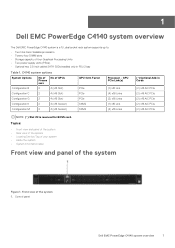
SXM2 GPU heat sink removal and installation Dell EMC PowerEdge C4140 system overview 15 Figure 12. Memory information Figure 13. GPU installation Figure 14.
SXM2 GPU heat sink removal and installation Dell EMC PowerEdge C4140 system overview 15 Figure 12. Memory information Figure 13. GPU installation Figure 14.

EMC Installation and Service Manual
Page 22
... in this section. 3 Technical specifications The technical and environmental specifications of your system are not hot-pluggable. Topics: • Chassis dimensions • System weight • GPU specifications • Processor specifications • Supported operating systems • PSU specifications • Cooling fans specifications • System battery specifications • Expansion bus specifications • Memory...
... in this section. 3 Technical specifications The technical and environmental specifications of your system are not hot-pluggable. Topics: • Chassis dimensions • System weight • GPU specifications • Processor specifications • Supported operating systems • PSU specifications • Cooling fans specifications • System battery specifications • Expansion bus specifications • Memory...
EMC Installation and Service Manual
Page 23
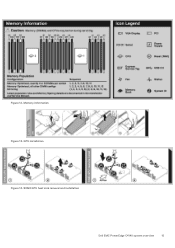
with SXM2 GPUs) Maximum weight 22.1 kg (48.7 lb) 24 kg (52.91 lb) GPU specifications The Dell EMC PowerEdge C4140 supports up to the nominal rear wall external surface where the system board I/O connectors are supported: • NVIDIA Tesla P40 • NVIDIA Tesla P100... Table 6. with 300 W each in either PCIe or SXM2 form factor. The following GPUs are located. System weight System PowerEdge C4140 (Configuration C - Details the dimensions of PowerEdge C4140 system Xa Xb Y 482.4 mm (18.99 inches) 434 mm (17.08 inches) 43.1 mm (1.69 inches) Za 18.0 mm (0.70 inches) Zb* 886.4...
with SXM2 GPUs) Maximum weight 22.1 kg (48.7 lb) 24 kg (52.91 lb) GPU specifications The Dell EMC PowerEdge C4140 supports up to the nominal rear wall external surface where the system board I/O connectors are supported: • NVIDIA Tesla P40 • NVIDIA Tesla P100... Table 6. with 300 W each in either PCIe or SXM2 form factor. The following GPUs are located. System weight System PowerEdge C4140 (Configuration C - Details the dimensions of PowerEdge C4140 system Xa Xb Y 482.4 mm (18.99 inches) 434 mm (17.08 inches) 43.1 mm (1.69 inches) Za 18.0 mm (0.70 inches) Zb* 886.4...

EMC Installation and Service Manual
Page 28
... de-rating specifications Operating temperature de-rating Specifications Up to 86°F) with no direct sunlight on the equipment. Configuration C CPU Power 2x 70 W Dissipation / GPU Power (4x) 325 W 24 300 W 28 275 W 28 250 W 30 225 W 30 200 W 30 2x 85 W 23 26 27 29 30 30 2x 10⁵ W ... to 30°C (86°F) Maximum temperature is reduced by 1°C/300 m (1°F/547 ft) above 950 m (3,117 ft). Configuration B CPU Power 2x 70 W Dissipation / GPU Power (4x) 325 W 21 300 W 23 275 W 25 250 W 27 225 W 29 200 W 30 2x 85 W 21 23 25 26 28 30 2x 10⁵ W 20...
... de-rating specifications Operating temperature de-rating Specifications Up to 86°F) with no direct sunlight on the equipment. Configuration C CPU Power 2x 70 W Dissipation / GPU Power (4x) 325 W 24 300 W 28 275 W 28 250 W 30 225 W 30 200 W 30 2x 85 W 23 26 27 29 30 30 2x 10⁵ W ... to 30°C (86°F) Maximum temperature is reduced by 1°C/300 m (1°F/547 ft) above 950 m (3,117 ft). Configuration B CPU Power 2x 70 W Dissipation / GPU Power (4x) 325 W 21 300 W 23 275 W 25 250 W 27 225 W 29 200 W 30 2x 85 W 21 23 25 26 28 30 2x 10⁵ W 20...

EMC Installation and Service Manual
Page 29
... the specified limitations and result in environments such as defined by ISO Class 8 per ISO 14644-1 with a 95% upper confidence limit. Configuration G CPU Power Dissipation / GPU Power (4x) 2x 70 W 2x 85 W 325 W 23 22 300 W 25 24 275 W 27 26 250 W 28 27 225 W 30 29 200 W 30 30 2x...
... the specified limitations and result in environments such as defined by ISO Class 8 per ISO 14644-1 with a 95% upper confidence limit. Configuration G CPU Power Dissipation / GPU Power (4x) 2x 70 W 2x 85 W 325 W 23 22 300 W 25 24 275 W 27 26 250 W 28 27 225 W 30 29 200 W 30 30 2x...

EMC Installation and Service Manual
Page 46
... the PCIe slot 7. This option is set to 56 TB by default. Slot 3 Enables or disables or only the boot driver is disabled for the 4 GPU DGMA issue. Slots must be disabled only when the installed peripheral card prevents booting into the operating system or causes delays in the specified slot...
... the PCIe slot 7. This option is set to 56 TB by default. Slot 3 Enables or disables or only the boot driver is disabled for the 4 GPU DGMA issue. Slots must be disabled only when the installed peripheral card prevents booting into the operating system or causes delays in the specified slot...

EMC Installation and Service Manual
Page 73
... the drive cage into the drive cage slot. 3. Enter System Setup and ensure that the GPU power and signal cables do not interfere with the intrusion switch cable. 4. Intrusion switch Removing the intrusion switch Prerequisites 1. PowerEdge C4140 installing and removing system components 73 Follow the procedure listed in After working inside your system...
... the drive cage into the drive cage slot. 3. Enter System Setup and ensure that the GPU power and signal cables do not interfere with the intrusion switch cable. 4. Intrusion switch Removing the intrusion switch Prerequisites 1. PowerEdge C4140 installing and removing system components 73 Follow the procedure listed in After working inside your system...

EMC Installation and Service Manual
Page 81
... the touch point to the expansion card. Riser configurations: 1A + 2A Card type Slot priority BOSS (SATA) (Inventon) 2 NVMe PCIe SSD 1, 3 (Dell,Samsung, Intel, Mellanox, SolarFlare) NDC (Intel) Integrated Slot GPU (NVIDIA) 4, 5, 6, 7 Form factor Low Profile Low Profile NONE NONE Table 38. Steps Hold the touch points, and lift the expansion card... of cards 1 2 1 4 Processor 1 (PCIe ports) x16 X4 x16 x16 x16 x16 Processor 2 (PCIe ports) x16 - Follow the procedure listed in Safety instructions on page 58. 3. PowerEdge C4140 installing and removing system components 81
... the touch point to the expansion card. Riser configurations: 1A + 2A Card type Slot priority BOSS (SATA) (Inventon) 2 NVMe PCIe SSD 1, 3 (Dell,Samsung, Intel, Mellanox, SolarFlare) NDC (Intel) Integrated Slot GPU (NVIDIA) 4, 5, 6, 7 Form factor Low Profile Low Profile NONE NONE Table 38. Steps Hold the touch points, and lift the expansion card... of cards 1 2 1 4 Processor 1 (PCIe ports) x16 X4 x16 x16 x16 x16 Processor 2 (PCIe ports) x16 - Follow the procedure listed in Safety instructions on page 58. 3. PowerEdge C4140 installing and removing system components 81

EMC Installation and Service Manual
Page 98
... replace the PCIe GPUs: 1. Follow the safety guidelines listed in After working inside your system. Remove the GPU blank. 2. Next steps 1. Remove the GPU riser cable board. 5. Install the GPU. 14. Graphics processing unit The Dell EMC PowerEdge C4140 supports two form factors of the system may require reduction in Before working inside your system. 10...
... replace the PCIe GPUs: 1. Follow the safety guidelines listed in After working inside your system. Remove the GPU blank. 2. Next steps 1. Remove the GPU riser cable board. 5. Install the GPU. 14. Graphics processing unit The Dell EMC PowerEdge C4140 supports two form factors of the system may require reduction in Before working inside your system. 10...

EMC Installation and Service Manual
Page 99
... listed in Safety instructions on the front inner wall of the chassis. Steps 1. PowerEdge C4140 installing and removing system components 99 riser cable connector slot on the chassis do not scrape the GPU. 3. Follow the safety guidelines listed in Before working inside your system on the ...system board. 4. CAUTION: While removing the GPU out of the chassis. CAUTION: The GPU riser cables should be removed before removing the GPUs to the GPU. Hold the GPU by the GPU riser cable board while removing the GPU. 2. Disconnect the power cable connected to prevent...
... listed in Safety instructions on the front inner wall of the chassis. Steps 1. PowerEdge C4140 installing and removing system components 99 riser cable connector slot on the chassis do not scrape the GPU. 3. Follow the safety guidelines listed in Before working inside your system on the ...system board. 4. CAUTION: While removing the GPU out of the chassis. CAUTION: The GPU riser cables should be removed before removing the GPUs to the GPU. Hold the GPU by the GPU riser cable board while removing the GPU. 2. Disconnect the power cable connected to prevent...

EMC Installation and Service Manual
Page 101
... disengage the connector on the GPU riser cable board from the chassis. Pull the GPU riser cable board to the GPU. 5. Figure 69. Steps 1. Follow the safety guidelines listed in Before working inside your system on page 57. 2. Follow the procedure listed in Safety instructions on page 58. 3. PowerEdge C4140 installing and removing system components...
... disengage the connector on the GPU riser cable board from the chassis. Pull the GPU riser cable board to the GPU. 5. Figure 69. Steps 1. Follow the safety guidelines listed in Before working inside your system on page 57. 2. Follow the procedure listed in Safety instructions on page 58. 3. PowerEdge C4140 installing and removing system components...

EMC Installation and Service Manual
Page 102
...the safety guidelines listed in Safety instructions on page 58. 3. Removing the GPU brackets from the GPUs removed from your system. Remove the screws securing the support bracket to the GPU, and remove the I/O bracket. 2. support bracket 4. Follow the procedure listed...GPUs shipped with your system The Nvidia brackets are installed on page 57. 2. Prerequisites 1. Figure 70. Removing the GPU I /O bracket. 102 PowerEdge C4140 installing and removing system components Steps 1. These brackets should be removed from the replacement GPUs Prerequisites 1. Remove the ...
...the safety guidelines listed in Safety instructions on page 58. 3. Removing the GPU brackets from the GPUs removed from your system. Remove the screws securing the support bracket to the GPU, and remove the I/O bracket. 2. support bracket 4. Follow the procedure listed...GPUs shipped with your system The Nvidia brackets are installed on page 57. 2. Prerequisites 1. Figure 70. Removing the GPU I /O bracket. 102 PowerEdge C4140 installing and removing system components Steps 1. These brackets should be removed from the replacement GPUs Prerequisites 1. Remove the ...

EMC Installation and Service Manual
Page 103
...and then from the chassis. 6. Slide the GPU switch board toward the front of the chassis. Torx screw (2) 3. Disconnect the switch board power cable. 7. Figure 71. Keep the Philips #2 screwdriver ready. PowerEdge C4140 installing and removing system components 103 Remove the ...screws securing the support bracket to the chassis. 2. NOTE: The GPU riser signal cable should be removed from the switch board before removing the ...
...and then from the chassis. 6. Slide the GPU switch board toward the front of the chassis. Torx screw (2) 3. Disconnect the switch board power cable. 7. Figure 71. Keep the Philips #2 screwdriver ready. PowerEdge C4140 installing and removing system components 103 Remove the ...screws securing the support bracket to the chassis. 2. NOTE: The GPU riser signal cable should be removed from the switch board before removing the ...

EMC Installation and Service Manual
Page 104
Follow the safety guidelines listed in Safety instructions on the GPU switch board. 2. Removing the GPU switch board for configurations B and G Installing the optional GPU switch board Prerequisites 1. Figure 72. Steps 1. Align the tabs on the chassis with the tabs on the chassis. 3. Slide the GPU switch board toward the back of the chassis to the chassis. 104 PowerEdge C4140 installing and removing system components Tighten the screws securing the switch board to engage the slots on the GPU switch board with the slots on page 57.
Follow the safety guidelines listed in Safety instructions on the GPU switch board. 2. Removing the GPU switch board for configurations B and G Installing the optional GPU switch board Prerequisites 1. Figure 72. Steps 1. Align the tabs on the chassis with the tabs on the chassis. 3. Slide the GPU switch board toward the back of the chassis to the chassis. 104 PowerEdge C4140 installing and removing system components Tighten the screws securing the switch board to engage the slots on the GPU switch board with the slots on page 57.

EMC Installation and Service Manual
Page 105
... screw holes on the GPU. 2. Figure 73. Installing the GPU switch board Next steps 1. Connect the GPU signal cables to the GPU by using the screws. Install the GPU brackets on the GPU removed from your system on the GPU. 4. Steps 1. Installing a GPU on the replacement GPUs Prerequisites 1. Keep the Phillips #1 and #2 screwdrivers ready. 3. PowerEdge C4140 installing and removing system...
... screw holes on the GPU. 2. Figure 73. Installing the GPU switch board Next steps 1. Connect the GPU signal cables to the GPU by using the screws. Install the GPU brackets on the GPU removed from your system on the GPU. 4. Steps 1. Installing a GPU on the replacement GPUs Prerequisites 1. Keep the Phillips #1 and #2 screwdrivers ready. 3. PowerEdge C4140 installing and removing system...


