Getting Started Guide
Page 5
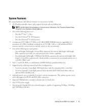
...8226; A minimum of 512 MB of 533-MHz or 667-MHz DDR2 SDRAM memory, upgradable to two internal, 1-inch high, SATA hard drives with the integrated drive controllers. - One full-height, half-length, 133MHz/64 bit PCI-X expansion slot and one full-height, half-length PCIe expansion ... an optional SAS controller card. • Optional remote access controller for PCI-X and PCIe RAC connectors. • Optional USB flash drive emulates a diskette drive or hard drive. • One 345-W power supply. • Two integrated Gigabit Ethernet network adapters, capable of supporting 10-Mbps, 100-Mbps,...
...8226; A minimum of 512 MB of 533-MHz or 667-MHz DDR2 SDRAM memory, upgradable to two internal, 1-inch high, SATA hard drives with the integrated drive controllers. - One full-height, half-length, 133MHz/64 bit PCI-X expansion slot and one full-height, half-length PCIe expansion ... an optional SAS controller card. • Optional remote access controller for PCI-X and PCIe RAC connectors. • Optional USB flash drive emulates a diskette drive or hard drive. • One 345-W power supply. • Two integrated Gigabit Ethernet network adapters, capable of supporting 10-Mbps, 100-Mbps,...
Getting Started Guide
Page 12
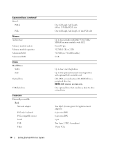
... 2.0 compliant 15-pin VGA Expansion Buses (continued) Riser 2 PCI-X PCIe Memory Architecture Memory module sockets Memory module capacities Minimum RAM Maximum RAM Drives Hard Drives SATA SAS Optical drive USB flash drive Connectors Externally accessible Back Network adapter PS/2-style keyboard PS/2-compatible mouse Serial USB Video 10 Getting Started With Your System One full...
... 2.0 compliant 15-pin VGA Expansion Buses (continued) Riser 2 PCI-X PCIe Memory Architecture Memory module sockets Memory module capacities Minimum RAM Maximum RAM Drives Hard Drives SATA SAS Optical drive USB flash drive Connectors Externally accessible Back Network adapter PS/2-style keyboard PS/2-compatible mouse Serial USB Video 10 Getting Started With Your System One full...
Hardware Owner's Manual (PDF)
Page 4
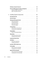
... Cooling Shroud 47 Installing the Cooling Shroud 48 System Battery 49 Replacing the System Battery 49 Optical Drive 50 Removing the Optical Drive 50 Installing the Optical Drive 51 Configuring the Boot Drive 52 Hard Drives 52 Removing a Hard Drive 52 Installing a Hard Drive 56 Installing a SAS Controller Card 57 Fan Assembly 57 Removing the Fan Assembly 57 Installing the...
... Cooling Shroud 47 Installing the Cooling Shroud 48 System Battery 49 Replacing the System Battery 49 Optical Drive 50 Removing the Optical Drive 50 Installing the Optical Drive 51 Configuring the Boot Drive 52 Hard Drives 52 Removing a Hard Drive 52 Installing a Hard Drive 56 Installing a SAS Controller Card 57 Fan Assembly 57 Removing the Fan Assembly 57 Installing the...
Hardware Owner's Manual (PDF)
Page 6
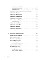
... 86 Troubleshooting System Cooling Problems 87 Troubleshooting a Fan 87 Troubleshooting System Memory 88 Troubleshooting an Optical Drive 89 Troubleshooting a Hard Drive 90 Troubleshooting Expansion Cards 91 Troubleshooting the Microprocessor 92 5 Running the System Diagnostics 93 Using Dell PowerEdge Diagnostics 93 System Diagnostics Features 93 When to Use the System Diagnostics 94 Running the System Diagnostics...
... 86 Troubleshooting System Cooling Problems 87 Troubleshooting a Fan 87 Troubleshooting System Memory 88 Troubleshooting an Optical Drive 89 Troubleshooting a Hard Drive 90 Troubleshooting Expansion Cards 91 Troubleshooting the Microprocessor 92 5 Running the System Diagnostics 93 Using Dell PowerEdge Diagnostics 93 System Diagnostics Features 93 When to Use the System Diagnostics 94 Running the System Diagnostics...

Hardware Owner's Manual (PDF)
Page 12
...lights or blinks to indicate the status of the current operating system state. The power-on indicator, power button 2 Diagnostic indicators (4) 3 USB connectors (2) 4 Hard-drive activity indicator 5 Video connector Description The power button turns system power off and power is disconnected from the standby state, briefly press the power button... Program" on . The indicator is off when the system is off and on page 29 and the operating system's documentation. The green hard-drive activity indicator flashes when the hard drives are in diagnosing and troubleshooting the system.
...lights or blinks to indicate the status of the current operating system state. The power-on indicator, power button 2 Diagnostic indicators (4) 3 USB connectors (2) 4 Hard-drive activity indicator 5 Video connector Description The power button turns system power off and power is disconnected from the standby state, briefly press the power button... Program" on . The indicator is off when the system is off and on page 29 and the operating system's documentation. The green hard-drive activity indicator flashes when the hard drives are in diagnosing and troubleshooting the system.

Hardware Owner's Manual (PDF)
Page 13
... due to do so by qualified support personnel or by the operating system's documentation. Optional 3.5-inch SAS or SATA hard drive. Optional. When one of the buttons is pushed, the blue system status indicators on the front and back panels ...directed to a system problem. Front-Panel Components (continued) Item Component Icon 6 System status indicator 7 System identification button 8 Hard drive 1 9 Hard drive 0 10 Optical drive 11 Bezel 12 NMI button Description The blue system status indicator lights up during normal system operation. You can be pressed using...
... due to do so by qualified support personnel or by the operating system's documentation. Optional 3.5-inch SAS or SATA hard drive. Optional. When one of the buttons is pushed, the blue system status indicators on the front and back panels ...directed to a system problem. Front-Panel Components (continued) Item Component Icon 6 System status indicator 7 System identification button 8 Hard drive 1 9 Hard drive 0 10 Optical drive 11 Bezel 12 NMI button Description The blue system status indicator lights up during normal system operation. You can be pressed using...
Hardware Owner's Manual (PDF)
Page 16
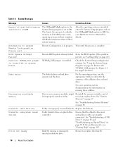
Retry the BIOS update. Data error The diskette drive or hard drive cannot read failure Faulty or improperly inserted diskette. See "System Memory" on page 29. Reinsert or replace the diskette. 16 About Your System This... documentation for details. Please wait.... Decreasing available memory One or more than 2 GB of the diskette drive or hard drive. Replace the diskette. See "Troubleshooting a USB Device" on page 83 and "Troubleshooting an Optical Drive" on page 88. Remote Configuration is set the OS Install Mode option to 256MB The OS Install ...
Retry the BIOS update. Data error The diskette drive or hard drive cannot read failure Faulty or improperly inserted diskette. See "System Memory" on page 29. Reinsert or replace the diskette. 16 About Your System This... documentation for details. Please wait.... Decreasing available memory One or more than 2 GB of the diskette drive or hard drive. Replace the diskette. See "Troubleshooting a USB Device" on page 83 and "Troubleshooting an Optical Drive" on page 88. Remote Configuration is set the OS Install Mode option to 256MB The OS Install ...

Hardware Owner's Manual (PDF)
Page 18
...read failure at address, read value expecting value Memory tests terminated by The spacebar was pressed during Information only. ensure that the hard drive is installed, properly seated, and partitioned as a boot device. information for details. properly installed. No boot device available The system... About Your System Enter the System Setup program and verify the boot sequence information. See your Hardware Owner's Manual for the hard drive. If the message continues to terminate the memory test. "Running the System Diagnostics" on the system board might verify the ...
...read failure at address, read value expecting value Memory tests terminated by The spacebar was pressed during Information only. ensure that the hard drive is installed, properly seated, and partitioned as a boot device. information for details. properly installed. No boot device available The system... About Your System Enter the System Setup program and verify the boot sequence information. See your Hardware Owner's Manual for the hard drive. If the message continues to terminate the memory test. "Running the System Diagnostics" on the system board might verify the ...
Hardware Owner's Manual (PDF)
Page 19
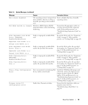
...operating system is trying to boot Insert a diskette that has a bootable from a diskette that all appropriate cables are properly connected. See "Troubleshooting a Hard Drive" on page 63. If the problem persists, see "Getting Help" on page 91. If the problem persists, see "Getting Help" on page ...103. See Figure 6-1 for a BIOS update. Ensure that the hard drive cables are securely connected to install PCI device BIOS (Option ROM) checksum failure is n Faulty or improperly installed PCIe card in the specified slot...
...operating system is trying to boot Insert a diskette that has a bootable from a diskette that all appropriate cables are properly connected. See "Troubleshooting a Hard Drive" on page 63. If the problem persists, see "Getting Help" on page 91. If the problem persists, see "Getting Help" on page ...103. See Figure 6-1 for a BIOS update. Ensure that the hard drive cables are securely connected to install PCI device BIOS (Option ROM) checksum failure is n Faulty or improperly installed PCIe card in the specified slot...
Hardware Owner's Manual (PDF)
Page 20
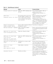
... system. See "Troubleshooting a USB Device" on page 83, "Troubleshooting a Hard Drive" on page 90, or "Troubleshooting a Hard Drive" on page 90. ROM bad checksum = address Faulty or improperly installed expansion card. Parameters failure. SATA port 0/1 hard disk drive failure SATA port 0/1 hard disk drive auto-sensing error Faulty drive. drive configuration error Ensure that all memory modules are properly installed...
... system. See "Troubleshooting a USB Device" on page 83, "Troubleshooting a Hard Drive" on page 90, or "Troubleshooting a Hard Drive" on page 90. ROM bad checksum = address Faulty or improperly installed expansion card. Parameters failure. SATA port 0/1 hard disk drive failure SATA port 0/1 hard disk drive auto-sensing error Faulty drive. drive configuration error Ensure that all memory modules are properly installed...
Hardware Owner's Manual (PDF)
Page 21
... or Date settings; If the problem persists, see "Getting Help" on page 68. If the problem persists, see "Troubleshooting the System Battery" on the boot hard disk hard drive. Invalid memory configuration. See "Memory Module Installation Guidelines" on page 103. If the problem persists, see "Getting Help" on page 103. See system battery...
... or Date settings; If the problem persists, see "Getting Help" on page 68. If the problem persists, see "Troubleshooting the System Battery" on the boot hard disk hard drive. Invalid memory configuration. See "Memory Module Installation Guidelines" on page 103. If the problem persists, see "Getting Help" on page 103. See system battery...
Hardware Owner's Manual (PDF)
Page 22
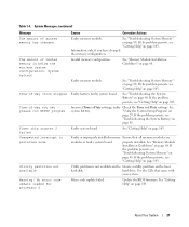
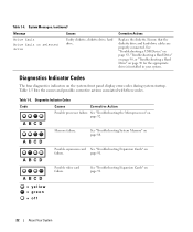
...corrective actions associated with these codes. Table 1-5. See "Troubleshooting the Microprocessor" on selected drive Causes Faulty diskette, diskette drive, hard drive. page 91. Ensure that the diskette drive and hard-drive cables are properly connected. System Messages (continued) Message Write fault Write fault on page... 92. See "Troubleshooting a USB Device" on page 83, "Troubleshooting a Hard Drive" on page 90, or "Troubleshooting a Hard Drive" on the system front panel display error codes during system startup. Diagnostics Indicator Codes The four ...
...corrective actions associated with these codes. Table 1-5. See "Troubleshooting the Microprocessor" on selected drive Causes Faulty diskette, diskette drive, hard drive. page 91. Ensure that the diskette drive and hard-drive cables are properly connected. System Messages (continued) Message Write fault Write fault on page... 92. See "Troubleshooting a USB Device" on page 83, "Troubleshooting a Hard Drive" on page 90, or "Troubleshooting a Hard Drive" on the system front panel display error codes during system startup. Diagnostics Indicator Codes The four ...

Hardware Owner's Manual (PDF)
Page 23
...off Memory configuration See "Troubleshooting System Memory" on page 83. Table 1-5. See "Installing a Hard Drive" on page 103. Ensure that the diskette drive and hard-drive are properly connected. Corrective Action Ensure that the optical drive and hard drives are properly connected. page 88. Possible system board resource and/or system board hardware failure. ...Diagnostic Indicator Codes (continued) Code A B C D Causes Diskette drive or hard drive failure. Possible expansion card See "Troubleshooting Expansion Cards" on page 103. About ...
...off Memory configuration See "Troubleshooting System Memory" on page 83. Table 1-5. See "Installing a Hard Drive" on page 103. Ensure that the diskette drive and hard-drive are properly connected. Corrective Action Ensure that the optical drive and hard drives are properly connected. page 88. Possible system board resource and/or system board hardware failure. ...Diagnostic Indicator Codes (continued) Code A B C D Causes Diskette drive or hard drive failure. Possible expansion card See "Troubleshooting Expansion Cards" on page 103. About ...
Hardware Owner's Manual (PDF)
Page 32
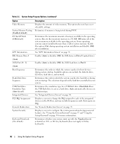
...Determines the maximum amount of video memory. Enables (Auto) or disables (Off) the IDE device in which the system searches the hard drives during operating system installation and disable (Off) after installation. Displays a screen to 84-key keyboards). 32 Using the System Setup ...Program See "Using the System Password" on page 37 and "Using the Setup Password" on the hard drives installed in Port 0. Available options can include the diskette drive, CD drive, hard drives, and network. Table 2-2. See "Integrated Devices Screen" on page 35. Some operating systems cannot ...
...Determines the maximum amount of video memory. Enables (Auto) or disables (Off) the IDE device in which the system searches the hard drives during operating system installation and disable (Off) after installation. Displays a screen to 84-key keyboards). 32 Using the System Setup ...Program See "Using the System Password" on page 37 and "Using the Setup Password" on the hard drives installed in Port 0. Available options can include the diskette drive, CD drive, hard drives, and network. Table 2-2. See "Integrated Devices Screen" on page 35. Some operating systems cannot ...
Hardware Owner's Manual (PDF)
Page 43
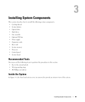
Installing System Components This section describes how to install the following system components: • Cooling shroud • System battery • Optical drive • Hard drives • Fan assembly • Optional PCI fan • Power supply • Expansion cards • Riser card • System memory • Processor • Control panel • ...
Installing System Components This section describes how to install the following system components: • Cooling shroud • System battery • Optical drive • Hard drives • Fan assembly • Optional PCI fan • Power supply • Expansion cards • Riser card • System memory • Processor • Control panel • ...
Hardware Owner's Manual (PDF)
Page 44
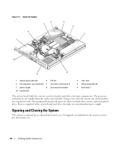
...bays provide space for up to the system board and drives through one nonredundant power supply. Opening and Closing the System The system is supplied to two hard drives and an optional optical drive. The processor and memory are installed directly on the... Inside the System 2 1 4 3 5 6 7 10 8 9 1 optical drive (optional) 2 4 PCI expansion card (optional) 5 7 power supply 8 10 hard drive 0 PCI fan processor and heat sink processor fan module 3 riser card 6 memory modules (4) 9 hard drive 1 The system board holds the system's control circuitry and other electronic components.
...bays provide space for up to the system board and drives through one nonredundant power supply. Opening and Closing the System The system is supplied to two hard drives and an optional optical drive. The processor and memory are installed directly on the... Inside the System 2 1 4 3 5 6 7 10 8 9 1 optical drive (optional) 2 4 PCI expansion card (optional) 5 7 power supply 8 10 hard drive 0 PCI fan processor and heat sink processor fan module 3 riser card 6 memory modules (4) 9 hard drive 1 The system board holds the system's control circuitry and other electronic components.

Hardware Owner's Manual (PDF)
Page 50
.... 1 Open the system. See "Installing the Riser Card" on page 48. 10 Close the system. Removing the Optical Drive CAUTION: Only trained service technicians are authorized to the hard drive 0 carrier. See "Installing the Cooling Shroud" on page 67. 9 Install the cooling shroud. An interposer card is connected...11 Enter the System Setup program to confirm that secures the optical drive to enter the correct time and date. See "Closing the System" on top of the drive which allows the drive to be connected to the back of hard drive 0. See "Opening the System" on the System Setup screens,...
.... 1 Open the system. See "Installing the Riser Card" on page 48. 10 Close the system. Removing the Optical Drive CAUTION: Only trained service technicians are authorized to the hard drive 0 carrier. See "Installing the Cooling Shroud" on page 67. 9 Install the cooling shroud. An interposer card is connected...11 Enter the System Setup program to confirm that secures the optical drive to enter the correct time and date. See "Closing the System" on top of the drive which allows the drive to be connected to the back of hard drive 0. See "Opening the System" on the System Setup screens,...

Hardware Owner's Manual (PDF)
Page 51
Removing and Installing the Optional Optical Drive 2 3 4 1 5 7 6 1 interposer board 4 retaining pins (4) 7 hard drive 0 2 captive fasteners (2) 5 mounting holes (4) 3 interface cable 6 bracket release lever Installing the Optical Drive CAUTION: Only trained service technicians are authorized to remove the system ... inside the system. See "Closing the System" on the hard drive 0 bracket. Figure 3-6. See Figure 3-6. 2 Rotate the drive downward until they snap into place. 3 Connect the interposer card to the optical drive's interposer card. 5 Close the system. Push the plungers ...
Removing and Installing the Optional Optical Drive 2 3 4 1 5 7 6 1 interposer board 4 retaining pins (4) 7 hard drive 0 2 captive fasteners (2) 5 mounting holes (4) 3 interface cable 6 bracket release lever Installing the Optical Drive CAUTION: Only trained service technicians are authorized to remove the system ... inside the system. See "Closing the System" on the hard drive 0 bracket. Figure 3-6. See Figure 3-6. 2 Rotate the drive downward until they snap into place. 3 Connect the interposer card to the optical drive's interposer card. 5 Close the system. Push the plungers ...

Hardware Owner's Manual (PDF)
Page 52
.... See the documentation that accompanied the controller card. See "Removing the Optical Drive" on the system board. Removing a Hard Drive The procedures for SATA hard drives are the same. See Figure 6-2 for hard drive 1 are connected to a controller card. 4 Pull up to a SAS ...the system. Configuring the Boot Drive The drive or device from the hard drive. To boot the system from a hard drive or drive array, the drive(s) must be connected to the appropriate controller: • For systems using the integrated hard-drive controller, the master drive (drive 0) must be connected to...
.... See the documentation that accompanied the controller card. See "Removing the Optical Drive" on the system board. Removing a Hard Drive The procedures for SATA hard drives are the same. See Figure 6-2 for hard drive 1 are connected to a controller card. 4 Pull up to a SAS ...the system. Configuring the Boot Drive The drive or device from the hard drive. To boot the system from a hard drive or drive array, the drive(s) must be connected to the appropriate controller: • For systems using the integrated hard-drive controller, the master drive (drive 0) must be connected to...

Hardware Owner's Manual (PDF)
Page 53
Removing the HDD0 Hard-Drive Carrier 1 2 3 4 6 1 HDD0 hard-drive carrier 4 plunger 5 2 interface cable 5 notches (4) 3 power cable 6 tabs (4) Installing System Components 53 Figure 3-7.
Removing the HDD0 Hard-Drive Carrier 1 2 3 4 6 1 HDD0 hard-drive carrier 4 plunger 5 2 interface cable 5 notches (4) 3 power cable 6 tabs (4) Installing System Components 53 Figure 3-7.


