Dell PowerEdge Systems Microprocessor Upgrade Guide
Page 8
... in the upgrade kit into the diskette drive and reboot the system. 2. Insert the BIOS diskette provided in this document. 1-4 Dell PowerEdge Systems - After the system completes the boot routine, follow the online instructions to save the current system configuration information. When the welcome... 2. Select Step 5: Save and Exit, and then follow the instructions on that diskette by performing the following steps: a. Removing the covers. Rotating the power supply. Reboot the system. 3. Disconnecting power and peripheral cables. See your BIOS with your kit, update your system...
... in the upgrade kit into the diskette drive and reboot the system. 2. Insert the BIOS diskette provided in this document. 1-4 Dell PowerEdge Systems - After the system completes the boot routine, follow the online instructions to save the current system configuration information. When the welcome... 2. Select Step 5: Save and Exit, and then follow the instructions on that diskette by performing the following steps: a. Removing the covers. Rotating the power supply. Reboot the system. 3. Disconnecting power and peripheral cables. See your BIOS with your kit, update your system...
Dell PowerEdge Systems Microprocessor Upgrade Guide
Page 9
...resetting the chassis intrusion detector. See "Removing and Replacing the Cooling Shroud", found later in this document. c. support.dell.com Dell PowerEdge Systems - See "Installing the Upgrade Microprocessors", found later in the System Setup program by someone else, contact your computer... and peripherals to Not Detected. See "Installing a New Cooling Shroud", found later in this document. 6. Replace the covers and front ...
...resetting the chassis intrusion detector. See "Removing and Replacing the Cooling Shroud", found later in this document. c. support.dell.com Dell PowerEdge Systems - See "Installing the Upgrade Microprocessors", found later in the System Setup program by someone else, contact your computer... and peripherals to Not Detected. See "Installing a New Cooling Shroud", found later in this document. 6. Replace the covers and front ...
Dell PowerEdge Systems Microprocessor Upgrade Guide
Page 10
...the front bezel. Replacing the system board mounting plate or tray. See your PowerEdge 2300, the system board mounting plate must be replaced. Run the Dell Diagnostics to Pentium II or Pentium III microprocessors in your system Installation and ...cooling fan shroud. Applies only when installing 600 MHz or greater microprocessors. Removing the covers. See your User's Guide and your computer Installation and Troubleshooting Guide for specific instructions, if needed. 1-6 Dell PowerEdge Systems - A replacement mounting plate is operating correctly. e.
...the front bezel. Replacing the system board mounting plate or tray. See your PowerEdge 2300, the system board mounting plate must be replaced. Run the Dell Diagnostics to Pentium II or Pentium III microprocessors in your system Installation and ...cooling fan shroud. Applies only when installing 600 MHz or greater microprocessors. Removing the covers. See your User's Guide and your computer Installation and Troubleshooting Guide for specific instructions, if needed. 1-6 Dell PowerEdge Systems - A replacement mounting plate is operating correctly. e.
Dell PowerEdge Systems Microprocessor Upgrade Guide
Page 11
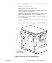
b. d. mounting screws (3) system board and mounting-plate assembly support.dell.com Dell PowerEdge Systems - a. Remove the right- Record the location of the system, locate and remove the three screws that secure the system board and mounting... of any internal expansion card cables, and then record the slot number assignments and remove all the expansion cards. e. At the left -side computer covers. c. f. Record the locations and disconnect all external peripheral cables from their connectors on a grounded antistatic mat or other antistatic surface. Place the expansion...
b. d. mounting screws (3) system board and mounting-plate assembly support.dell.com Dell PowerEdge Systems - a. Remove the right- Record the location of the system, locate and remove the three screws that secure the system board and mounting... of any internal expansion card cables, and then record the slot number assignments and remove all the expansion cards. e. At the left -side computer covers. c. f. Record the locations and disconnect all external peripheral cables from their connectors on a grounded antistatic mat or other antistatic surface. Place the expansion...
Dell PowerEdge Systems Microprocessor Upgrade Guide
Page 13
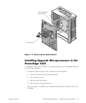
... system board mounting tray as you will come to the system board. a. Unlock and remove the computer cover. Slide the system board 6.3 mm (0.25 inch) toward the front (left edge of the chassis. support.dell.com Dell PowerEdge Systems - Lay the tray assembly with the system board facing up on a grounded antistatic mat or... tray out of the mounting tray, as shown in this document. f. To install the upgrade mounting tray assembly (provided in your upgrade kit) in your PowerEdge 4300 system, perform the preceding steps in antistatic bags or on a flat surface.
... system board mounting tray as you will come to the system board. a. Unlock and remove the computer cover. Slide the system board 6.3 mm (0.25 inch) toward the front (left edge of the chassis. support.dell.com Dell PowerEdge Systems - Lay the tray assembly with the system board facing up on a grounded antistatic mat or... tray out of the mounting tray, as shown in this document. f. To install the upgrade mounting tray assembly (provided in your upgrade kit) in your PowerEdge 4300 system, perform the preceding steps in antistatic bags or on a flat surface.
Dell PowerEdge Systems Microprocessor Upgrade Guide
Page 15
c. d. Microprocessor Upgrade 1-11 Disconnecting power and peripheral cables. b. support.dell.com Dell PowerEdge Systems - Removing the cooling fan shroud. See your system Installation and Troubleshooting Guide for specific instructions, if needed. inner card-guide brackets (6) thumbscrew To upgrade to Pentium II or Pentium III microprocessors in the PowerEdge 4350, perform the following steps: a. Removing the front bezel. Access the system board, which involves the following steps: 1. Removing the covers.
c. d. Microprocessor Upgrade 1-11 Disconnecting power and peripheral cables. b. support.dell.com Dell PowerEdge Systems - Removing the cooling fan shroud. See your system Installation and Troubleshooting Guide for specific instructions, if needed. inner card-guide brackets (6) thumbscrew To upgrade to Pentium II or Pentium III microprocessors in the PowerEdge 4350, perform the following steps: a. Removing the front bezel. Access the system board, which involves the following steps: 1. Removing the covers.
Dell PowerEdge Systems Microprocessor Upgrade Guide
Page 19
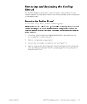
To remove the cooling shroud, perform the following steps. 1. Remove the right-side computer cover. 3. Microprocessor Upgrade 1-15 Remove the shroud by lifting the end of the shroud disengages from the electrical outlet. 2. Turn off the system, including any attached ... system back panel. sor(s) until the opposite end of the shroud closest to the microproces- Unscrew and remove the two retention pins (see Figure 1-7). 4. support.dell.com Dell PowerEdge Systems - You may need to remove this shroud to improve airflow over the microprocessors.
To remove the cooling shroud, perform the following steps. 1. Remove the right-side computer cover. 3. Microprocessor Upgrade 1-15 Remove the shroud by lifting the end of the shroud disengages from the electrical outlet. 2. Turn off the system, including any attached ... system back panel. sor(s) until the opposite end of the shroud closest to the microproces- Unscrew and remove the two retention pins (see Figure 1-7). 4. support.dell.com Dell PowerEdge Systems - You may need to remove this shroud to improve airflow over the microprocessors.
Dell PowerEdge Systems Microprocessor Upgrade Guide
Page 23
... and modifying entries in the System Setup program. Microprocessor Upgrade 1-19 Close the computer panel doors (for PowerEdge 4350 systems only) or replace the covers and front bezel, and reconnect your computer and peripherals to verify that the top line in the System Setup... the system boots, it detects the presence of Pentium III microprocessors are not displayed. Run the Dell Diagnostics to their power sources and turn them on. support.dell.com Dell PowerEdge Systems - To reassemble the system and perform verification checks, perform the following message appears: Second ...
... and modifying entries in the System Setup program. Microprocessor Upgrade 1-19 Close the computer panel doors (for PowerEdge 4350 systems only) or replace the covers and front bezel, and reconnect your computer and peripherals to verify that the top line in the System Setup... the system boots, it detects the presence of Pentium III microprocessors are not displayed. Run the Dell Diagnostics to their power sources and turn them on. support.dell.com Dell PowerEdge Systems - To reassemble the system and perform verification checks, perform the following message appears: Second ...

Dell PowerEdge 4350 System Upgrade Installation Guide
Page 8
Provide for personal injury or shock. 4 Dell PowerEdge 4350 System Upgrade Installation Guide Verify the receipt and condition of all upgrade components. 6. Unpack the upgrade components. 5. Ground yourself by touching an unpainted metal surface ... the card-slot openings at the back of all boxes and components. 4. Doing so reduces the potential for a suitable workspace that you remove the computer covers, perform the following steps: 1. Check and verify the physical condition of the computer, before touching anything inside your computer. you start the upgrade, be sure...
Provide for personal injury or shock. 4 Dell PowerEdge 4350 System Upgrade Installation Guide Verify the receipt and condition of all upgrade components. 6. Unpack the upgrade components. 5. Ground yourself by touching an unpainted metal surface ... the card-slot openings at the back of all boxes and components. 4. Doing so reduces the potential for a suitable workspace that you remove the computer covers, perform the following steps: 1. Check and verify the physical condition of the computer, before touching anything inside your computer. you start the upgrade, be sure...

Dell PowerEdge 4350 System Upgrade Installation Guide
Page 14
... edge of the third power supply. See "SCSI Backplane" in Chapter 4 of the Service Manual for more information. 2. Remove the top-cover panel. Replace the top-cover panel. 6. fan assembly air dam shroud fan assembly grip slot (release lever inside the slot) Inspect the fan assembly cavity for the air... See "Front Bezel" in Chapter 4 of the Service Manual for more information. 3. Orient the air dam shroud as shown in place. 5. Replace the bezel. 10 Dell PowerEdge 4350 System Upgrade Installation Guide If the air dam shroud is not installed, perform the following steps: 1.
... edge of the third power supply. See "SCSI Backplane" in Chapter 4 of the Service Manual for more information. 2. Remove the top-cover panel. Replace the top-cover panel. 6. fan assembly air dam shroud fan assembly grip slot (release lever inside the slot) Inspect the fan assembly cavity for the air... See "Front Bezel" in Chapter 4 of the Service Manual for more information. 3. Orient the air dam shroud as shown in place. 5. Replace the bezel. 10 Dell PowerEdge 4350 System Upgrade Installation Guide If the air dam shroud is not installed, perform the following steps: 1.

