Installing a SATA Optical Drive
Page 1
Dell™ PowerEdge™ 19x0 and 29x0 Systems Installing a SATA Optical Drive
Dell™ PowerEdge™ 19x0 and 29x0 Systems Installing a SATA Optical Drive

Installing a SATA Optical Drive
Page 3
...: Disconnect and remove the SAS controller daughter card. See your Hardware Owner's Manual. 3 Remove the system cover. Removing an Existing Optical Drive - Installing a SATA Optical Drive These instructions apply to Dell™ PowerEdge™ systems to remove the system cover and access any of the components inside the system. WARNING: Only trained service technicians...
...: Disconnect and remove the SAS controller daughter card. See your Hardware Owner's Manual. 3 Remove the system cover. Removing an Existing Optical Drive - Installing a SATA Optical Drive These instructions apply to Dell™ PowerEdge™ systems to remove the system cover and access any of the components inside the system. WARNING: Only trained service technicians...
Installing a SATA Optical Drive
Page 4
... the back of the tray. PowerEdge 2970, 2950, and 1950 For PowerEdge 2970 and 2950 systems, the optical drive tray that shipped with the SATA drive installation kit. Replacing a PowerEdge 2950 or 2970 Optical Drive NOTE: If you are replacing an existing IDE optical drive, you are replacing an existing optical drive, do not require optical drive trays. See Figure 1-1. 5 Lower the...
... the back of the tray. PowerEdge 2970, 2950, and 1950 For PowerEdge 2970 and 2950 systems, the optical drive tray that shipped with the SATA drive installation kit. Replacing a PowerEdge 2950 or 2970 Optical Drive NOTE: If you are replacing an existing IDE optical drive, you are replacing an existing optical drive, do not require optical drive trays. See Figure 1-1. 5 Lower the...

Installing a SATA Optical Drive
Page 5
Spread the side rails of the replacement drive tray and insert the back end of the drive. Replacing the Optical Drive in a PowerEdge 2950 or 2970 System 2 1 3 4 5 6 7 1 optical drive 3 interposer 5 SATA power cable 7 optical drive carrier 2 interposer release latch 4 SATA cable 6 carrier latch Replacing a PowerEdge 1950 Optical Drive NOTE: The replacement drive tray provided in the installation kit must be used...
Spread the side rails of the replacement drive tray and insert the back end of the drive. Replacing the Optical Drive in a PowerEdge 2950 or 2970 System 2 1 3 4 5 6 7 1 optical drive 3 interposer 5 SATA power cable 7 optical drive carrier 2 interposer release latch 4 SATA cable 6 carrier latch Replacing a PowerEdge 1950 Optical Drive NOTE: The replacement drive tray provided in the installation kit must be used...

Installing a SATA Optical Drive
Page 6
...Figure 1-2. Installing a SATA Optical Drive in the optical drive kit. 4 Route the SATA cable to the power supply connector. PowerEdge 1950 1 Insert the optical drive tray into the system until it is fully inserted and locked into the cable path on top of the optical drive. 3 Connect the branching power ... cable toward the chipset shroud and insert the cable into position. 2 Connect the SATA cable (the end with a cable provided in a PowerEdge 1950 Drive Tray 2 3 1 4 5 1 optical drive 3 SATA power cable 5 optical drive carrier 2 SATA cable 4 carrier latch Installing the SATA Optical...
...Figure 1-2. Installing a SATA Optical Drive in the optical drive kit. 4 Route the SATA cable to the power supply connector. PowerEdge 1950 1 Insert the optical drive tray into the system until it is fully inserted and locked into the cable path on top of the optical drive. 3 Connect the branching power ... cable toward the chipset shroud and insert the cable into position. 2 Connect the SATA cable (the end with a cable provided in a PowerEdge 1950 Drive Tray 2 3 1 4 5 1 optical drive 3 SATA power cable 5 optical drive carrier 2 SATA cable 4 carrier latch Installing the SATA Optical...

Installing a SATA Optical Drive
Page 7
...See "SAS Controller Daughter Card" in your Hardware Owner's Manual. 7 Reconnect the system to the power supply connector. PowerEdge 2970 or 2950 1 Insert the optical drive tray into the system until it is fully inserted and locked into position. 2 Connect the SATA cable (the end... the branching power cable to power and turn on system board 4 system fans 6 optical drive 5 Reinstall the SAS controller daughter card and reconnect the SAS cable. Figure 1-3. See "Closing the System" in the PowerEdge 1950 2 1 3 4 6 5 1 SATA data cable 3 chipset shroud 5 SATA power cable 2 SATA_A ...
...See "SAS Controller Daughter Card" in your Hardware Owner's Manual. 7 Reconnect the system to the power supply connector. PowerEdge 2970 or 2950 1 Insert the optical drive tray into the system until it is fully inserted and locked into position. 2 Connect the SATA cable (the end... the branching power cable to power and turn on system board 4 system fans 6 optical drive 5 Reinstall the SAS controller daughter card and reconnect the SAS cable. Figure 1-3. See "Closing the System" in the PowerEdge 1950 2 1 3 4 6 5 1 SATA data cable 3 chipset shroud 5 SATA power cable 2 SATA_A ...

Installing a SATA Optical Drive
Page 8
... toward the front of the system until the bracket detaches from the chassis slots. 6 Route the SATA cable in the cable channel in the PowerEdge 2950 and 2970 1 2 3 4 5 1 SATA_B connector on the system board. SATA Cable Routing in the right wall of the cable retention bracket to the ... connect the cable to the SATA_B connector on system board 2 cable retention bracket 3 SATA data cable 4 SATA power cable 5 optical drive 8 Installing a SATA Optical Drive See Figure 1-4. 7 Route the SATA cable along the top of the chassis and replace the cable retention bracket over the cable.
... toward the front of the system until the bracket detaches from the chassis slots. 6 Route the SATA cable in the cable channel in the PowerEdge 2950 and 2970 1 2 3 4 5 1 SATA_B connector on the system board. SATA Cable Routing in the right wall of the cable retention bracket to the ... connect the cable to the SATA_B connector on system board 2 cable retention bracket 3 SATA data cable 4 SATA power cable 5 optical drive 8 Installing a SATA Optical Drive See Figure 1-4. 7 Route the SATA cable along the top of the chassis and replace the cable retention bracket over the cable.

Installing a SATA Optical Drive
Page 9
.... 10 Close the system. For a PowerEdge 1900 system, connect to the CD/TBU connector on the system backplane. For a PowerEdge 2900, use the SATA_D connector. PowerEdge 2900 and 1900 1 If the mounting screws are not attached to the drive, install them now. 2 Align the ...'s Manual. 11 Reconnect the system to the power supply as follows: - Installing a SATA Optical Drive 9 Installing the SATA Optical Drive - For a PowerEdge 1900, use the SATA_B connector. - For a PowerEdge 2900 system, connect to an available power supply cable. 5 Replace the center fan bracket. 9 Replace...
.... 10 Close the system. For a PowerEdge 1900 system, connect to the CD/TBU connector on the system backplane. For a PowerEdge 2900, use the SATA_D connector. PowerEdge 2900 and 1900 1 If the mounting screws are not attached to the drive, install them now. 2 Align the ...'s Manual. 11 Reconnect the system to the power supply as follows: - Installing a SATA Optical Drive 9 Installing the SATA Optical Drive - For a PowerEdge 1900, use the SATA_B connector. - For a PowerEdge 2900 system, connect to an available power supply cable. 5 Replace the center fan bracket. 9 Replace...

Installing a SATA Optical Drive
Page 10
Figure 1-5. SATA Cable Routing in your Hardware Owner's Manual. 10 Reconnect the system to the SAS controller daughter card. 9 Close the system. See "Closing the System" in a PowerEdge 2900 or 1900 3 2 4 5 1 1 optical drive 3 SATA data cable 5 SATA power connector on SAS backplane (PowerEdge 2900 only) 2 SATA power cable 4 SATA connector on system board 8 Reconnect the cables to power and turn on the system and attached peripherals. 10 Installing a SATA Optical Drive
Figure 1-5. SATA Cable Routing in your Hardware Owner's Manual. 10 Reconnect the system to the SAS controller daughter card. 9 Close the system. See "Closing the System" in a PowerEdge 2900 or 1900 3 2 4 5 1 1 optical drive 3 SATA data cable 5 SATA power connector on SAS backplane (PowerEdge 2900 only) 2 SATA power cable 4 SATA connector on system board 8 Reconnect the cables to power and turn on the system and attached peripherals. 10 Installing a SATA Optical Drive
Information Update
Page 4
3.5-Inch Chassis Update 13 Front Features and Indicators 13 Mixed SAS/SATA Hard Drive Configuration (3.5-Inch Drives Only 15 Removing a 3.5-Inch Drive Blank 15 Installing a 3.5-Inch Drive Blank 15 Removing the SAS/SATA Backplane Board . . . . 16 Installing the SAS Backplane Board 18 SAS/SATA Backplane Board Connectors . . . . . 19 4 Contents
3.5-Inch Chassis Update 13 Front Features and Indicators 13 Mixed SAS/SATA Hard Drive Configuration (3.5-Inch Drives Only 15 Removing a 3.5-Inch Drive Blank 15 Installing a 3.5-Inch Drive Blank 15 Removing the SAS/SATA Backplane Board . . . . 16 Installing the SAS Backplane Board 18 SAS/SATA Backplane Board Connectors . . . . . 19 4 Contents
Information Update
Page 5
...drives, physical memory, communications ports, NICs, CMOS, and more. To assess a system problem, first use the system diagnostics. Information Update 5 Using the Online Diagnostics The online Server Administrator Diagnostics tool mentioned in the section "Using Server Administration Diagnostics" in the Hardware Owner's Manual has been replaced by the online Dell PowerEdge...™ Diagnostics suite of diagnostic programs. Dell PowerEdge Diagnostics includes online diagnostic tests for the channel. Regional ...
...drives, physical memory, communications ports, NICs, CMOS, and more. To assess a system problem, first use the system diagnostics. Information Update 5 Using the Online Diagnostics The online Server Administrator Diagnostics tool mentioned in the section "Using Server Administration Diagnostics" in the Hardware Owner's Manual has been replaced by the online Dell PowerEdge...™ Diagnostics suite of diagnostic programs. Dell PowerEdge Diagnostics includes online diagnostic tests for the channel. Regional ...
Information Update
Page 15
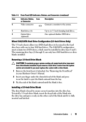
... with one to six 3.5-inch hot-plug hard drives. The remaining drive bays (2 through 5) can only have drive blanks installed. The SAS/SATA configuration must contain two SATA drives, which must have SAS hard drives or drive blanks installed. Table 1-5. Front-Panel LED Indicators,... Item Indicator, Button, Icon Description or Connector 6 Video connector Connects a monitor to the system. 7 Hard drives (6) 8 Optical drive (optional) Up to four SAS hard drives. See "Removing the Front Bezel" in your Hardware Owner's Manual. 2 Insert your finger under the shrouded...
... with one to six 3.5-inch hot-plug hard drives. The remaining drive bays (2 through 5) can only have drive blanks installed. The SAS/SATA configuration must contain two SATA drives, which must have SAS hard drives or drive blanks installed. Table 1-5. Front-Panel LED Indicators,... Item Indicator, Button, Icon Description or Connector 6 Video connector Connects a monitor to the system. 7 Hard drives (6) 8 Optical drive (optional) Up to four SAS hard drives. See "Removing the Front Bezel" in your Hardware Owner's Manual. 2 Insert your finger under the shrouded...
Information Update
Page 16
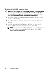
... inside the system. See Figure 1-3. See "Opening the System" in your Hardware Owner's Manual. 3 Open the drive-carrier release handle on each hard drive and partially extend all of the components inside the computer, and protecting against electrostatic discharge. 1 Turn off the system... and attached peripherals, and disconnect the system from the electrical outlet. 2 Open the system. See "Removing a Hot-Plug Hard Drive" in your Hardware Owner's Manual. 16 Information Update Removing the SAS/SATA Backplane Board WARNING: Only trained service technicians are authorized to ...
... inside the system. See Figure 1-3. See "Opening the System" in your Hardware Owner's Manual. 3 Open the drive-carrier release handle on each hard drive and partially extend all of the components inside the computer, and protecting against electrostatic discharge. 1 Turn off the system... and attached peripherals, and disconnect the system from the electrical outlet. 2 Open the system. See "Removing a Hot-Plug Hard Drive" in your Hardware Owner's Manual. 16 Information Update Removing the SAS/SATA Backplane Board WARNING: Only trained service technicians are authorized to ...
Information Update
Page 17
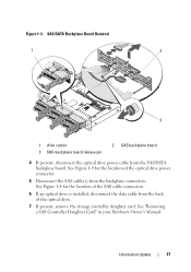
... Information Update 17 See Figure 1-4 for the location of the SAS cable connectors. 6 If an optical drive is installed, disconnect the data cable from the back of the optical drive power connector. 5 Disconnect the SAS cable(s) from the SAS/SATA backplane board. See Figure 1-4 for ...the location of the optical drive. 7 If present, remove the storage controller daughter card. See "Removing a SAS Controller ...
... Information Update 17 See Figure 1-4 for the location of the SAS cable connectors. 6 If an optical drive is installed, disconnect the data cable from the back of the optical drive power connector. 5 Disconnect the SAS cable(s) from the SAS/SATA backplane board. See Figure 1-4 for ...the location of the optical drive. 7 If present, remove the storage controller daughter card. See "Removing a SAS Controller ...
Information Update
Page 18
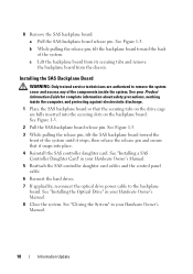
... Board WARNING: Only trained service technicians are fully inserted into place. 4 Reinstall the SAS controller daughter card. See "Installing the Optical Drive" in your Product Information Guide for complete information about safety precautions, working inside the system. 8 Remove the SAS backplane board: a ... 1 Place the SAS backplane board so that it stops, then release the release pin and ensure that the securing tabs on the drive cage are authorized to the backplane board. See "Installing a SAS Controller Daughter Card" in your Hardware Owner's Manual. 18 Information...
... Board WARNING: Only trained service technicians are fully inserted into place. 4 Reinstall the SAS controller daughter card. See "Installing the Optical Drive" in your Product Information Guide for complete information about safety precautions, working inside the system. 8 Remove the SAS backplane board: a ... 1 Place the SAS backplane board so that it stops, then release the release pin and ensure that the securing tabs on the drive cage are authorized to the backplane board. See "Installing a SAS Controller Daughter Card" in your Hardware Owner's Manual. 18 Information...
Information Update
Page 19
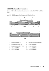
Figure 1-4. SAS Backplane Board Components: 3.5-inch x4 Option 1 2 3 10 9 8 front 7 6 4 5 back 1 primary SAS (SAS_A) 3 secondary SAS (SAS_B) 5 backplane power (BP_PWR) 7 drive 3 (SASDRV3) 9 drive 1 (SASDRV1) 2 optical drive power (CD_PWR) 4 drive 5 (SASDRV5) 6 drive 4 (SASDRV4) 8 drive 2 (SASDRV2) 10 drive 0 (SASDRV0) Information Update 19 SAS/SATA Backplane Board Connectors Figure 1-4 shows the location of the connectors on the SAS/SATA backplane board.
Figure 1-4. SAS Backplane Board Components: 3.5-inch x4 Option 1 2 3 10 9 8 front 7 6 4 5 back 1 primary SAS (SAS_A) 3 secondary SAS (SAS_B) 5 backplane power (BP_PWR) 7 drive 3 (SASDRV3) 9 drive 1 (SASDRV1) 2 optical drive power (CD_PWR) 4 drive 5 (SASDRV5) 6 drive 4 (SASDRV4) 8 drive 2 (SASDRV2) 10 drive 0 (SASDRV0) Information Update 19 SAS/SATA Backplane Board Connectors Figure 1-4 shows the location of the connectors on the SAS/SATA backplane board.
Getting Started Guide
Page 5
...It also provides information about booting from an external device attached to eight 2.5-inch, internal hot-pluggable Serial Attached SCSI (SAS) or SATA hard drives. • The optional media bay provides support for the latest support information about other documents you may need when setting up to a SAS or... SCSI adapter, including SAS 5/E, PERC 5/E, or PERC 4e/DC. See support.dell.com for an optional half-height tape backup unit (TBU) and an optional slim-line 1.44-MB diskette drive. • An optional slim-line IDE CD, DVD, or combination CD-RW/DVD...
...It also provides information about booting from an external device attached to eight 2.5-inch, internal hot-pluggable Serial Attached SCSI (SAS) or SATA hard drives. • The optional media bay provides support for the latest support information about other documents you may need when setting up to a SAS or... SCSI adapter, including SAS 5/E, PERC 5/E, or PERC 4e/DC. See support.dell.com for an optional half-height tape backup unit (TBU) and an optional slim-line 1.44-MB diskette drive. • An optional slim-line IDE CD, DVD, or combination CD-RW/DVD...

Getting Started Guide
Page 6
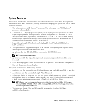
... subsystem based on an integrated ATI ES1000 33-MHz PCI video controller. For more information about specific features, see www.dell.com. 4 Getting Started With Your System • Four external USB 2.0-compliant connectors (two on the front and two on the back...) supporting a diskette drive, a DVD-ROM drive, a keyboard, a mouse, or a USB flash drive. • One internal USB 2.0-compliant connector supporting an optional bootable USB flash drive for customized boot configurations. • Optional remote access controller (RAC) for...
... subsystem based on an integrated ATI ES1000 33-MHz PCI video controller. For more information about specific features, see www.dell.com. 4 Getting Started With Your System • Four external USB 2.0-compliant connectors (two on the front and two on the back...) supporting a diskette drive, a DVD-ROM drive, a keyboard, a mouse, or a USB flash drive. • One internal USB 2.0-compliant connector supporting an optional bootable USB flash drive for customized boot configurations. • Optional remote access controller (RAC) for...

Getting Started Guide
Page 12
Memory Architecture Memory module sockets Memory module capacities Minimum RAM Maximum RAM Drives Hard drives Diskette drive Optical drive Tape drive Flash drive Connectors Back NIC Serial USB Video Front Video USB Internal USB 10 Getting Started With Your System 667-MHz registered parity DDR-II memory ...(32 GB (one processor) or 64 GB (two processors) when 8 GB memory modules are available) Up to eight 2.5-inch, hot-plug SAS or SATA internal drives One optional slimline 1.44-MB External optional USB 1.44-MB One optional slimline IDE CD, DVD, or combination CD-RW/DVD NOTE: DVD devices are...
Memory Architecture Memory module sockets Memory module capacities Minimum RAM Maximum RAM Drives Hard drives Diskette drive Optical drive Tape drive Flash drive Connectors Back NIC Serial USB Video Front Video USB Internal USB 10 Getting Started With Your System 667-MHz registered parity DDR-II memory ...(32 GB (one processor) or 64 GB (two processors) when 8 GB memory modules are available) Up to eight 2.5-inch, hot-plug SAS or SATA internal drives One optional slimline 1.44-MB External optional USB 1.44-MB One optional slimline IDE CD, DVD, or combination CD-RW/DVD NOTE: DVD devices are...
Hardware Owner's Manual
Page 3
Contents 1 About Your System 11 Other Information You May Need 11 Accessing System Features During Startup 12 Front-Panel Features and Indicators 13 Hard-Drive Indicator Codes 15 Back-Panel Features and Indicators 17 Connecting External Devices 17 Power Indicator Codes 18 NIC Indicator Codes 19 LCD Status Messages 20 ...
Contents 1 About Your System 11 Other Information You May Need 11 Accessing System Features During Startup 12 Front-Panel Features and Indicators 13 Hard-Drive Indicator Codes 15 Back-Panel Features and Indicators 17 Connecting External Devices 17 Power Indicator Codes 18 NIC Indicator Codes 19 LCD Status Messages 20 ...


