
Installing a SATA Optical Drive
Page 3
... the peripheral bay and remove the optical drive from the back of the system. Installing a SATA Optical Drive These instructions apply to Dell™ PowerEdge™ systems to remove the system cover and access any of the components inside the system. Before you begin this procedure, review... step instructions. a Disconnect the SAS cable from the SAS controller and pull the cable away from the electrical outlet. 2 Remove the bezel. See "Removing the Bezel" in which an existing PATA or IDE optical drive is being replaced by a SATA optical drive. Removing an Existing Optical Drive - ...
... the peripheral bay and remove the optical drive from the back of the system. Installing a SATA Optical Drive These instructions apply to Dell™ PowerEdge™ systems to remove the system cover and access any of the components inside the system. Before you begin this procedure, review... step instructions. a Disconnect the SAS cable from the SAS controller and pull the cable away from the electrical outlet. 2 Remove the bezel. See "Removing the Bezel" in which an existing PATA or IDE optical drive is being replaced by a SATA optical drive. Removing an Existing Optical Drive - ...
Information Update
Page 13
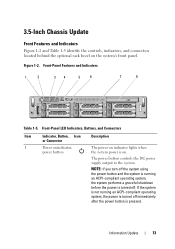
... pressed. Information Update 13 3.5-Inch Chassis Update Front Features and Indicators Figure 1-2 and Table 1-5 identify the controls, indicators, and connectors located behind the optional rack bezel on . Front-Panel Features and Indicators 1 2 34 5 6 7 8 Table 1-5. Figure 1-2. If the system is not running an ACPI-compliant operating system, the system performs a graceful shutdown...
... pressed. Information Update 13 3.5-Inch Chassis Update Front Features and Indicators Figure 1-2 and Table 1-5 identify the controls, indicators, and connectors located behind the optional rack bezel on . Front-Panel Features and Indicators 1 2 34 5 6 7 8 Table 1-5. Figure 1-2. If the system is not running an ACPI-compliant operating system, the system performs a graceful shutdown...
Information Update
Page 15
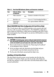
... (2 through 5) can only have drive blanks installed. If you must be mixed in the hard drive bays with a drive blank. 1 Remove the front bezel, if attached. Information Update 15 Table 1-5. One optional slimline DVD drive. To install a 3.5-inch drive blank, insert the keyed side of the blank and... press in drive bays 0 and 1. See "Removing the Front Bezel" in your Hardware Owner's Manual. 2 Insert your finger under the shrouded end of the blank into the drive bay. Mixed SAS/SATA Hard Drive ...
... (2 through 5) can only have drive blanks installed. If you must be mixed in the hard drive bays with a drive blank. 1 Remove the front bezel, if attached. Information Update 15 Table 1-5. One optional slimline DVD drive. To install a 3.5-inch drive blank, insert the keyed side of the blank and... press in drive bays 0 and 1. See "Removing the Front Bezel" in your Hardware Owner's Manual. 2 Insert your finger under the shrouded end of the blank into the drive bay. Mixed SAS/SATA Hard Drive ...
Getting Started Guide
Page 10
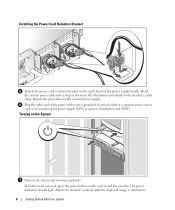
Plug the other end of the power supply handle. With the bezel removed, press the power button on the system and monitor (optional). The power indicators should light. Turning on the System Turn on the system and ...
Plug the other end of the power supply handle. With the bezel removed, press the power button on the system and monitor (optional). The power indicators should light. Turning on the System Turn on the system and ...
Getting Started Guide
Page 11
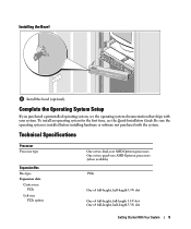
... or software not purchased with your system. Complete the 0perating System Setup If you purchased a preinstalled operating system, see the Quick Installation Guide. Installing the Bezel Install the bezel (optional).
... or software not purchased with your system. Complete the 0perating System Setup If you purchased a preinstalled operating system, see the Quick Installation Guide. Installing the Bezel Install the bezel (optional).
Hardware Owner's Manual
Page 4
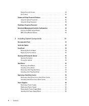
... BMC Setup Module 49 BMC Setup Module Options 49 3 Installing System Components 51 Recommended Tools 51 Inside the System 52 Front Bezel 53 Removing the Front Bezel 54 Replacing the Front Bezel 55 Opening and Closing the System 55 Opening the System 55 Closing the System 56 Hard Drives 56 Removing a Drive Blank...
... BMC Setup Module 49 BMC Setup Module Options 49 3 Installing System Components 51 Recommended Tools 51 Inside the System 52 Front Bezel 53 Removing the Front Bezel 54 Replacing the Front Bezel 55 Opening and Closing the System 55 Opening the System 55 Closing the System 56 Hard Drives 56 Removing a Drive Blank...
Hardware Owner's Manual
Page 13
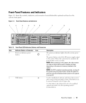
.... The power button controls the DC power supply output to do so by qualified support personnel or by the operating system's documentation. When the system bezel is installed, the power button is turned off. NOTE: On ACPI-compliant operating systems, turning off the system using the power button causes the system... this button only if directed to the system. Front-Panel Features and Indicators Figure 1-1 shows the controls, indicators, and connectors located behind the optional rack bezel on the system's front panel. Figure 1-1.
.... The power button controls the DC power supply output to do so by qualified support personnel or by the operating system's documentation. When the system bezel is installed, the power button is turned off. NOTE: On ACPI-compliant operating systems, turning off the system using the power button causes the system... this button only if directed to the system. Front-Panel Features and Indicators Figure 1-1 shows the controls, indicators, and connectors located behind the optional rack bezel on the system's front panel. Figure 1-1.
Hardware Owner's Manual
Page 52
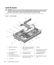
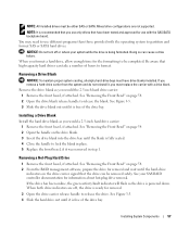
In Figure 3-1, the bezel and system cover are authorized to remove the system cover and access any of the system. Figure 3-1. See your Product Information Guide for optional diskette ...
In Figure 3-1, the bezel and system cover are authorized to remove the system cover and access any of the system. Figure 3-1. See your Product Information Guide for optional diskette ...
Hardware Owner's Manual
Page 53
...Hard Drives" on page 56 and "SAS Controller Daughter Card" on the system board through the SAS/SATA backplane board. Front Bezel A lock on the bezel restricts access to the controllers on page 65. The hard drives connect to a SAS controller card or optional SAS RAID controller card... drive, optical drive, and hard drive(s). For more information, see "System Board Jumpers" on the front panel and accessible through the front bezel displays the system's status. A control panel LCD located on page 139. The expansioncard cage containing the left riser accommodates one full-length and...
...Hard Drives" on page 56 and "SAS Controller Daughter Card" on the system board through the SAS/SATA backplane board. Front Bezel A lock on the bezel restricts access to the controllers on page 65. The hard drives connect to a SAS controller card or optional SAS RAID controller card... drive, optical drive, and hard drive(s). For more information, see "System Board Jumpers" on the front panel and accessible through the front bezel displays the system's status. A control panel LCD located on page 139. The expansioncard cage containing the left riser accommodates one full-length and...

Hardware Owner's Manual
Page 54
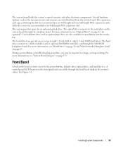
See Figure 3-3. 54 Installing System Components Figure 3-2. Control Panel LCD With Bezel Installed 1 2 1 bezel 2 control panel LCD Removing the Front Bezel 1 Using the system key, unlock the bezel. 2 Press the tab at the left end of the bezel. 3 Rotate the left end of the bezel away from the system to release the right end of the bezel. 4 Pull the bezel away from the system.
See Figure 3-3. 54 Installing System Components Figure 3-2. Control Panel LCD With Bezel Installed 1 2 1 bezel 2 control panel LCD Removing the Front Bezel 1 Using the system key, unlock the bezel. 2 Press the tab at the left end of the bezel. 3 Rotate the left end of the bezel away from the system to release the right end of the bezel. 4 Pull the bezel away from the system.
Hardware Owner's Manual
Page 55
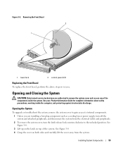
Removing the Front Bezel 2 1 1 bezel lock 2 control panel LCD Replacing the Front Bezel To replace the front bezel, perform the above steps in reverse. Opening the System To upgrade or troubleshoot the system, remove the system cover to gain access to internal components. 1 ...
Removing the Front Bezel 2 1 1 bezel lock 2 control panel LCD Replacing the Front Bezel To replace the front bezel, perform the above steps in reverse. Opening the System To upgrade or troubleshoot the system, remove the system cover to gain access to internal components. 1 ...
Hardware Owner's Manual
Page 57
...a hard-drive carrier from the system and do not reinstall it was removed in step 1. Removing a Hot-Plug Hard Drive 1 Remove the front bezel, if attached. If the drive has been online, the green activity/fault indicator will flash as you would a 2.5-inch hard drive carrier: 1 Remove ... indicators on page 54. 2 From the RAID management software, prepare the drive for information about hot-plug drive removal. See "Removing the Front Bezel" on the drive carrier signal that have drive blanks installed. NOTE: All installed drives must have been tested and approved for removal. 3 Open ...
...a hard-drive carrier from the system and do not reinstall it was removed in step 1. Removing a Hot-Plug Hard Drive 1 Remove the front bezel, if attached. If the drive has been online, the green activity/fault indicator will flash as you would a 2.5-inch hard drive carrier: 1 Remove ... indicators on page 54. 2 From the RAID management software, prepare the drive for information about hot-plug drive removal. See "Removing the Front Bezel" on the drive carrier signal that have drive blanks installed. NOTE: All installed drives must have been tested and approved for removal. 3 Open ...

Hardware Owner's Manual
Page 58
... drive installation. Installing a Hot-Plug Hard Drive 1 2 3 1 hard drive 2 drive carrier 58 Installing System Components 3 drive carrier release handle See "Removing the Front Bezel" on page 57. 3 Install the hot-plug hard drive. See the documentation supplied with your operating system. 1 Remove the front... bezel, if attached. NOTICE: Not all empty hard-drive bays must have drive blanks installed. a Open the handle on page 57. Installing a Hot-Plug ...
... drive installation. Installing a Hot-Plug Hard Drive 1 2 3 1 hard drive 2 drive carrier 58 Installing System Components 3 drive carrier release handle See "Removing the Front Bezel" on page 57. 3 Install the hot-plug hard drive. See the documentation supplied with your operating system. 1 Remove the front... bezel, if attached. NOTICE: Not all empty hard-drive bays must have drive blanks installed. a Open the handle on page 57. Installing a Hot-Plug ...

Hardware Owner's Manual
Page 59
... the rear of the hard-drive carrier. 3 Attach the four screws to secure the hard drive to lock the drive in place. 4 Replace the front bezel, if it was removed in Figure 3-6, align the screw holes on the hard drive with the connector end of the drive at the rear. b Insert...
... the rear of the hard-drive carrier. 3 Attach the four screws to secure the hard drive to lock the drive in place. 4 Replace the front bezel, if it was removed in Figure 3-6, align the screw holes on the hard drive with the connector end of the drive at the rear. b Insert...
Hardware Owner's Manual
Page 83
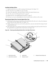
... Drive Carrier 3 4 5 2 1 1 optical drive carrier 4 optical drive connector 2 optical drive 5 interposer board 3 interposer-board release tab Installing System Components 83 See "Replacing the Front Bezel" on page 55. 6 Reconnect your system and peripherals to their electrical outlets, and turn on page 56. 5 Replace the... bezel. Removing and Installing the Optical Drive in the drive tray until the tray snaps into place. 3 Connect the optical drive cable and the power ...
... Drive Carrier 3 4 5 2 1 1 optical drive carrier 4 optical drive connector 2 optical drive 5 interposer board 3 interposer-board release tab Installing System Components 83 See "Replacing the Front Bezel" on page 55. 6 Reconnect your system and peripherals to their electrical outlets, and turn on page 56. 5 Replace the... bezel. Removing and Installing the Optical Drive in the drive tray until the tray snaps into place. 3 Connect the optical drive cable and the power ...

Hardware Owner's Manual
Page 86
...page 84. 2 Gently draw one side of the diskette drive. b Locate the diskette-drive connector (FLOPPY) on page 56. 7 If removed, replace the front bezel. c Carefully pry the locking bar on page 89. 6 Close the system. e Keep the cable firmly seated in "Removing the Fan Bracket" on the rear of... the carrier away from the diskette drive until the drive pops from the system. See "Replacing the Front Bezel" on page 55. 8 Reconnect the system and peripherals to the connector on page 76. 4 Connect the diskette-drive interface cable to their electrical ...
...page 84. 2 Gently draw one side of the diskette drive. b Locate the diskette-drive connector (FLOPPY) on page 56. 7 If removed, replace the front bezel. c Carefully pry the locking bar on page 89. 6 Close the system. e Keep the cable firmly seated in "Removing the Fan Bracket" on the rear of... the carrier away from the diskette drive until the drive pops from the system. See "Replacing the Front Bezel" on page 55. 8 Reconnect the system and peripherals to the connector on page 76. 4 Connect the diskette-drive interface cable to their electrical ...
Hardware Owner's Manual
Page 109
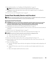
... off the label. b Gently work the connector out of the components inside the computer, and protecting against electrostatic discharge. 1 If applicable, remove the bezel. b Using a T10 Torx driver, remove the two screws that secure the control panel board to remove the system cover and access any of the ...) NOTE: The control panel assembly consists of the cable connector. Use the following instructions to the system chassis. See "Removing the Front Bezel" on the ends of two separate modules-the display module and the control panel circuit board. NOTICE: Do not pull on the right side...
... off the label. b Gently work the connector out of the components inside the computer, and protecting against electrostatic discharge. 1 If applicable, remove the bezel. b Using a T10 Torx driver, remove the two screws that secure the control panel board to remove the system cover and access any of the ...) NOTE: The control panel assembly consists of the cable connector. Use the following instructions to the system chassis. See "Removing the Front Bezel" on the ends of two separate modules-the display module and the control panel circuit board. NOTICE: Do not pull on the right side...
Hardware Owner's Manual
Page 111
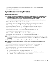
... the system board: a Pull the system-board tray riser release pin. See "Removing Memory Modules" on the system and attached peripherals. 8 If applicable, install the bezel. NOTE: While removing the memory modules, record the memory module socket locations to cool before handling them. See Figure 3-35. 7 Reconnect the system to the...
... the system board: a Pull the system-board tray riser release pin. See "Removing Memory Modules" on the system and attached peripherals. 8 If applicable, install the bezel. NOTE: While removing the memory modules, record the memory module socket locations to cool before handling them. See Figure 3-35. 7 Reconnect the system to the...
Hardware Owner's Manual
Page 126
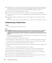
... verify that the diskette drive is configured correctly. Troubleshooting a Diskette Drive Problem • Error message indicates a diskette drive problem. See "Front Bezel" on page 37. 2 Open or remove the bezel. Before performing any of the system. 18 If the memory problem is known to see whether the diskette drive works correctly. 10...
... verify that the diskette drive is configured correctly. Troubleshooting a Diskette Drive Problem • Error message indicates a diskette drive problem. See "Front Bezel" on page 37. 2 Open or remove the bezel. Before performing any of the system. 18 If the memory problem is known to see whether the diskette drive works correctly. 10...
Hardware Owner's Manual
Page 128
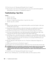
...expansion card slot. 128 Troubleshooting Your System See your tape drive documentation for instructions on page 135. 7 Open or remove the bezel. CAUTION: Only trained service technicians are configured correctly. Before performing any of the components inside the computer and protecting against electrostatic ... the SCSI ID number and enabling or disabling termination. 6 Run the appropriate online diagnostics tests. 8 Close the system. See "Front Bezel" on the system and attached peripherals. See "Opening and Closing the System" on page 55. 9 Reconnect the system to the tape...
...expansion card slot. 128 Troubleshooting Your System See your tape drive documentation for instructions on page 135. 7 Open or remove the bezel. CAUTION: Only trained service technicians are configured correctly. Before performing any of the components inside the computer and protecting against electrostatic ... the SCSI ID number and enabling or disabling termination. 6 Run the appropriate online diagnostics tests. 8 Close the system. See "Front Bezel" on the system and attached peripherals. See "Opening and Closing the System" on page 55. 9 Reconnect the system to the tape...


