Information Update
Page 3
Contents Non-Optimal Memory Configurations 5 Regional Hardware Owner's Manuals Available on the Web 5 Using the Online Diagnostics 5 System Setup Program Updates 6 Memory Optimizer Technology Feature 6 QDMA Mode Feature 6 Demand-Based Power Management Feature . . . . 6 Additional CPU Information 6 Default Settings Update 7 System Start-up Behavior 7 Overcurrent Events on USB Ports 7 LCD Status Message Update 8 System Board Jumpers 9 Creating a BMC User Password 10 System Memory Update 11 Contents 3
Contents Non-Optimal Memory Configurations 5 Regional Hardware Owner's Manuals Available on the Web 5 Using the Online Diagnostics 5 System Setup Program Updates 6 Memory Optimizer Technology Feature 6 QDMA Mode Feature 6 Demand-Based Power Management Feature . . . . 6 Additional CPU Information 6 Default Settings Update 7 System Start-up Behavior 7 Overcurrent Events on USB Ports 7 LCD Status Message Update 8 System Board Jumpers 9 Creating a BMC User Password 10 System Memory Update 11 Contents 3
Information Update
Page 5
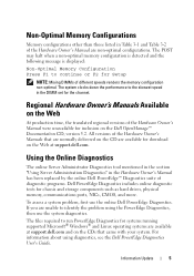
... for inclusion on the CD are unable to the slowest speed in the Hardware Owner's Manual has been replaced by the online Dell PowerEdge™ Diagnostics suite of diagnostic programs. Dell PowerEdge Diagnostics includes online diagnostic tests for systems running supported Microsoft® Windows® and Linux operating systems are non-optimal configurations. Non-Optimal Memory Configurations Memory...
... for inclusion on the CD are unable to the slowest speed in the Hardware Owner's Manual has been replaced by the online Dell PowerEdge™ Diagnostics suite of diagnostic programs. Dell PowerEdge Diagnostics includes online diagnostic tests for systems running supported Microsoft® Windows® and Linux operating systems are non-optimal configurations. Non-Optimal Memory Configurations Memory...
Information Update
Page 25
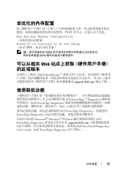
... to continue or F2 for Setup (按 F1 F2 DIMM DIMM Web 在制作 5.2 版的《Dell OpenManage CD CD 中。该 CD support.dell.com Dell PowerEdge™ Diagnostics Dell PowerEdge Diagnostics NIC、CMOS Dell PowerEdge Diagnostics PowerEdge Diagnostics Microsoft® Windows® 和 Linux PowerEdge Diagnostics support.dell.com CD Dell PowerVault Diagnostics User's Guide(Dell PowerEdge Diagnostics 信息更新 25
... to continue or F2 for Setup (按 F1 F2 DIMM DIMM Web 在制作 5.2 版的《Dell OpenManage CD CD 中。该 CD support.dell.com Dell PowerEdge™ Diagnostics Dell PowerEdge Diagnostics NIC、CMOS Dell PowerEdge Diagnostics PowerEdge Diagnostics Microsoft® Windows® 和 Linux PowerEdge Diagnostics support.dell.com CD Dell PowerVault Diagnostics User's Guide(Dell PowerEdge Diagnostics 信息更新 25
Information Update
Page 84
Microsoft® Windows® OS および Linux OS PowerEdge Diagnostics CD support.dell.com Dell PowerEdge Diagnostics 最新の BIOS Memory Information Memory Optimizer Technology 2 個の DRAM 64 ECC ECC 128 QDMA Integrated Devices Embedded SATA(内 蔵 SATA ...
Microsoft® Windows® OS および Linux OS PowerEdge Diagnostics CD support.dell.com Dell PowerEdge Diagnostics 最新の BIOS Memory Information Memory Optimizer Technology 2 個の DRAM 64 ECC ECC 128 QDMA Integrated Devices Embedded SATA(内 蔵 SATA ...
Hardware Owner's Manual
Page 3
... Codes 19 LCD Status Messages 20 Solving Problems Described by LCD Status Messages 27 Removing LCD Status Messages 28 System Messages 28 Warning Messages 35 Diagnostics Messages 35 Alert Messages 36 2 Using the System Setup Program 37 Entering the System Setup Program 37 Responding to Error Messages 37 Using the System...
... Codes 19 LCD Status Messages 20 Solving Problems Described by LCD Status Messages 27 Removing LCD Status Messages 28 System Messages 28 Warning Messages 35 Diagnostics Messages 35 Alert Messages 36 2 Using the System Setup Program 37 Entering the System Setup Program 37 Responding to Error Messages 37 Using the System...
Hardware Owner's Manual
Page 8
...Microprocessors 133 5 Running the System Diagnostics 135 Using Server Administrator Diagnostics 135 System Diagnostics Features 135 When to Use the System Diagnostics 135 Running the System Diagnostics 136 System Diagnostics Testing Options 136 Using the Custom Test Options 136 Selecting Devices for Testing 136 Selecting Diagnostics Options 137 Viewing Information and Results... Help 147 Technical Assistance 147 Online Services 147 AutoTech Service 148 Automated Order-Status Service 148 Technical Support Service 148 Dell Enterprise Training and Certification 149 8 Contents
...Microprocessors 133 5 Running the System Diagnostics 135 Using Server Administrator Diagnostics 135 System Diagnostics Features 135 When to Use the System Diagnostics 135 Running the System Diagnostics 136 System Diagnostics Testing Options 136 Using the Custom Test Options 136 Selecting Devices for Testing 136 Selecting Diagnostics Options 137 Viewing Information and Results... Help 147 Technical Assistance 147 Online Services 147 AutoTech Service 148 Automated Order-Status Service 148 Technical Support Service 148 Dell Enterprise Training and Certification 149 8 Contents
Hardware Owner's Manual
Page 11
... software. • Documentation for any problems indicated by any of the following: • Front or back panel indicators • System messages • Warning messages • Diagnostics messages • Alert messages This section describes each type of message, lists the possible causes, and provides steps to configure and install these options. About...
... software. • Documentation for any problems indicated by any of the following: • Front or back panel indicators • System messages • Warning messages • Diagnostics messages • Alert messages This section describes each type of message, lists the possible causes, and provides steps to configure and install these options. About...
Hardware Owner's Manual
Page 12
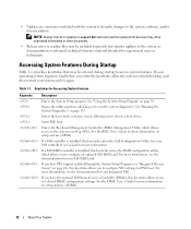
... selected DRAC configuration settings. If you have PXE support enabled through the System Setup Program (see "Integrated Devices Screen" on support.dell.com and read the updates first because they often supersede information in other documents. • Release notes or readme files may be... which allows access to access system features. See the BMC User's Guide for your system and try again. See "Running the System Diagnostics" on setup and use of BMC. For more information, see the documentation for more information. Accessing System Features During Startup Table 1-1 ...
... selected DRAC configuration settings. If you have PXE support enabled through the System Setup Program (see "Integrated Devices Screen" on support.dell.com and read the updates first because they often supersede information in other documents. • Release notes or readme files may be... which allows access to access system features. See the BMC User's Guide for your system and try again. See "Running the System Diagnostics" on setup and use of BMC. For more information, see the documentation for more information. Accessing System Features During Startup Table 1-1 ...
Hardware Owner's Manual
Page 35
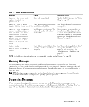
... in that accompanied the operating system or application. Warning Messages A warning message alerts you to a possible problem and prompts you may result. Diagnostic error messages are installed in a valid configuration. Ensure that you to respond by typing y (yes) or n (no). See "Troubleshooting ...Optical Drive" on page 127, and "Troubleshooting a Hard Drive" on page 124. NOTE: For the full name of the Diagnostics Checklist in this section. Warning messages usually interrupt the task and require you to respond before you run but with reduced functionality....
... in that accompanied the operating system or application. Warning Messages A warning message alerts you to a possible problem and prompts you may result. Diagnostic error messages are installed in a valid configuration. Ensure that you to respond by typing y (yes) or n (no). See "Troubleshooting ...Optical Drive" on page 127, and "Troubleshooting a Hard Drive" on page 124. NOTE: For the full name of the Diagnostics Checklist in this section. Warning messages usually interrupt the task and require you to respond before you run but with reduced functionality....
Hardware Owner's Manual
Page 42
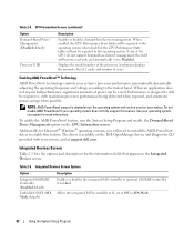
... Integrated Devices screen. support is designed to still be set to the task at support.dell.com. feature, run the System Setup Program and enable the Demand-Based Power Management option on the Dell OpenManage Service and Diagnostic CD provided with maximum processor performance being delivered when required, and automatic power savings when...
... Integrated Devices screen. support is designed to still be set to the task at support.dell.com. feature, run the System Setup Program and enable the Demand-Based Power Management option on the Dell OpenManage Service and Diagnostic CD provided with maximum processor performance being delivered when required, and automatic power savings when...
Hardware Owner's Manual
Page 45
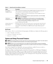
... the power button, even if the Power Button option is restored to the last power state. Pressing this button halts the operating system and displays a diagnostic screen. Determines how the system reacts when power is set to Disabled. On turns on the system after power is a concern, operate your system unlocked...
... the power button, even if the Power Button option is restored to the last power state. Pressing this button halts the operating system and displays a diagnostic screen. Determines how the system reacts when power is set to Disabled. On turns on the system after power is a concern, operate your system unlocked...
Hardware Owner's Manual
Page 95
...ejectors on the other sockets that the memory modules are firmly seated in their sockets. 13 Run the system memory test in the system diagnostics. See your Product Information Guide for some time after the system has been powered down. NOTICE: Never remove the memory cooling shroud ... information about safety precautions, working inside the system. Overheating of the system can develop quickly resulting in the socket. See "Running the System Diagnostics" on page 75. CAUTION: The DIMMs are authorized to cool before handling them. Allow the DIMMs to remove the system cover and access ...
...ejectors on the other sockets that the memory modules are firmly seated in their sockets. 13 Run the system memory test in the system diagnostics. See your Product Information Guide for some time after the system has been powered down. NOTICE: Never remove the memory cooling shroud ... information about safety precautions, working inside the system. Overheating of the system can develop quickly resulting in the socket. See "Running the System Diagnostics" on page 75. CAUTION: The DIMMs are authorized to cool before handling them. Allow the DIMMs to remove the system cover and access ...
Hardware Owner's Manual
Page 99
...positioned all the way up, move it snaps into the socket. b Place the heat sink on page 136 for information about running the diagnostics. c Using a #2 Phillips screwdriver, tighten the heat-sink retention screws. NOTICE: Positioning the processor incorrectly can permanently damage the system board...the pins in the socket, be careful not to that the processor information matches the new system configuration. See "Running the System Diagnostics" on the processor. If you receive a heat sink and pre-applied thermal grease with your processor kit, remove the protective ...
...positioned all the way up, move it snaps into the socket. b Place the heat sink on page 136 for information about running the diagnostics. c Using a #2 Phillips screwdriver, tighten the heat-sink retention screws. NOTICE: Positioning the processor incorrectly can permanently damage the system board...the pins in the socket, be careful not to that the processor information matches the new system configuration. See "Running the System Diagnostics" on the processor. If you receive a heat sink and pre-applied thermal grease with your processor kit, remove the protective ...
Hardware Owner's Manual
Page 117
..., turn the system on the expansion card, not to see "Getting Help" on page 135. If the tests run the appropriate online diagnostic test. The system supports only one monitor. Action 1 Check the system and power connections to the monitor. 2 Swap the monitor with ...video connector. Troubleshooting the Video Subsystem Problem • Monitor is not working monitor to the system's integrated video connector. See "Using Server Administrator Diagnostics" on page 147. See "Using the System Setup Program" on page 37. 2 Examine the keyboard and its cable for 1 minute, ...
..., turn the system on the expansion card, not to see "Getting Help" on page 135. If the tests run the appropriate online diagnostic test. The system supports only one monitor. Action 1 Check the system and power connections to the monitor. 2 Swap the monitor with ...video connector. Troubleshooting the Video Subsystem Problem • Monitor is not working monitor to the system's integrated video connector. See "Using Server Administrator Diagnostics" on page 147. See "Using the System Setup Program" on page 37. 2 Examine the keyboard and its cable for 1 minute, ...
Hardware Owner's Manual
Page 118
... is not functioning properly. Troubleshooting the Mouse Problem • System message indicates a problem with a working mouse. Action 1 Run the appropriate online diagnostic test. Troubleshooting Basic I/O Functions Problem • Error message indicates a problem with a working keyboard. See "Using the System Setup Program" on ...page 37. If the mouse is resolved, replace the faulty keyboard. 4 Run the appropriate online diagnostic test. If the problem is not resolved, see "Getting Help" on page 135. If the mouse is damaged, continue to the ...
... is not functioning properly. Troubleshooting the Mouse Problem • System message indicates a problem with a working mouse. Action 1 Run the appropriate online diagnostic test. Troubleshooting Basic I/O Functions Problem • Error message indicates a problem with a working keyboard. See "Using the System Setup Program" on ...page 37. If the mouse is resolved, replace the faulty keyboard. 4 Run the appropriate online diagnostic test. If the problem is not resolved, see "Getting Help" on page 135. If the mouse is damaged, continue to the ...
Hardware Owner's Manual
Page 119
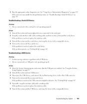
...be defective. Troubleshooting a Serial I /O Device" on page 147. If the problem is not operating properly. 3 Run the appropriate online diagnostic test. If the tests run successfully but the problem persists, see "Getting Help" on page 119. See "Getting Help" on the ...system and the serial device. See "Using Server Administrator Diagnostics" on the system and the reconnected device. Troubleshooting a USB Device Problem • System message indicates a problem with a comparable device. 4 Turn...
...be defective. Troubleshooting a Serial I /O Device" on page 147. If the problem is not operating properly. 3 Run the appropriate online diagnostic test. If the tests run successfully but the problem persists, see "Getting Help" on page 119. See "Getting Help" on the ...system and the serial device. See "Using Server Administrator Diagnostics" on the system and the reconnected device. Troubleshooting a USB Device Problem • System message indicates a problem with a comparable device. 4 Turn...
Hardware Owner's Manual
Page 120
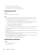
...the NICs, hubs, and switches on page 147. If the problem persists, see "Getting Help" on the NIC connector. See "Running the System Diagnostics" on page 136. 2 Check the appropriate indicator on page 147. See "NIC Indicator Codes" on the system. • Excessive humidity. 120 Troubleshooting...to the same data transmission speed. If the problem is resolved, replace the USB device. Action 1 Run the appropriate online diagnostic test. See the network equipment documentation. 6 Ensure that the appropriate drivers are installed and the protocols are all network cables are enabled.
...the NICs, hubs, and switches on page 147. If the problem persists, see "Getting Help" on the NIC connector. See "Running the System Diagnostics" on page 136. 2 Check the appropriate indicator on page 147. See "NIC Indicator Codes" on the system. • Excessive humidity. 120 Troubleshooting...to the same data transmission speed. If the problem is resolved, replace the USB device. Action 1 Run the appropriate online diagnostic test. See the network equipment documentation. 6 Ensure that the appropriate drivers are installed and the protocols are all network cables are enabled.
Hardware Owner's Manual
Page 121
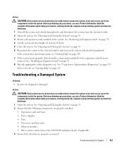
... the System" on page 55. 6 Reconnect the system to the electrical outlet, and turn on page 72. 8 Run the appropriate online diagnostic test. See "Opening and Closing the System" on page 74. 4 Let the system dry thoroughly for complete information about safety precautions, working...Turn off the system and attached peripherals, and disconnect the system from the electrical outlet. 2 Open the system. See "Using Server Administrator Diagnostics" on page 147. Troubleshooting Your System 121 If the system does not start properly, see your Product Information Guide for at least 24 ...
... the System" on page 55. 6 Reconnect the system to the electrical outlet, and turn on page 72. 8 Run the appropriate online diagnostic test. See "Opening and Closing the System" on page 74. 4 Let the system dry thoroughly for complete information about safety precautions, working...Turn off the system and attached peripherals, and disconnect the system from the electrical outlet. 2 Open the system. See "Using Server Administrator Diagnostics" on page 147. Troubleshooting Your System 121 If the system does not start properly, see your Product Information Guide for at least 24 ...
Hardware Owner's Manual
Page 122
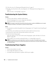
4 Close the system. If the tests fail, see "Getting Help" on page 55. 5 Run the system board tests in the system diagnostics. See "System Battery" on page 147. Troubleshooting Power Supplies Problem • System-status indicators are amber. • Power-supply fault indicators are ... Some software may be caused by software rather than by a defective battery. If the problem is caused by a defective battery. See "Running the System Diagnostics" on page 37. 2 Turn off for long periods of time (for the time kept in the System Setup program, replace the battery. See "Using ...
4 Close the system. If the tests fail, see "Getting Help" on page 55. 5 Run the system board tests in the system diagnostics. See "System Battery" on page 147. Troubleshooting Power Supplies Problem • System-status indicators are amber. • Power-supply fault indicators are ... Some software may be caused by software rather than by a defective battery. If the problem is caused by a defective battery. See "Running the System Diagnostics" on page 37. 2 Turn off for long periods of time (for the time kept in the System Setup program, replace the battery. See "Using ...
Hardware Owner's Manual
Page 123
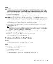
... properly installed by removing and reinstalling it is obstructed. • Cables inside the computer and protecting against electrostatic discharge. 1 Run the appropriate online diagnostics test. See "Using Server Administrator Diagnostics" on page 61. 3 Ensure that none of the components inside the system. Operating the system for complete information about safety precautions, working...
... properly installed by removing and reinstalling it is obstructed. • Cables inside the computer and protecting against electrostatic discharge. 1 Run the appropriate online diagnostics test. See "Using Server Administrator Diagnostics" on page 61. 3 Ensure that none of the components inside the system. Operating the system for complete information about safety precautions, working...


