

Getting Started Guide
Page 5
... 1.44-MB, 3.5-inch diskette drive. • An optional slim-line IDE CD, DVD, or combination CD-RW/DVD drive. The upgrade kit from Dell. NOTE: DVD devices are installed. • Support for up to six 3.5-inch, internal hot-pluggable Serial Attached SCSI (SAS) or SATA hard drives without... system cooling fans. Getting Started With Your System 3 To take advantage of this feature, you must order the processor upgrade kits from Dell contains the correct version of the processor, heat sink, and fan as well as additional processors. Either feature is available on the system board.
... 1.44-MB, 3.5-inch diskette drive. • An optional slim-line IDE CD, DVD, or combination CD-RW/DVD drive. The upgrade kit from Dell. NOTE: DVD devices are installed. • Support for up to six 3.5-inch, internal hot-pluggable Serial Attached SCSI (SAS) or SATA hard drives without... system cooling fans. Getting Started With Your System 3 To take advantage of this feature, you must order the processor upgrade kits from Dell contains the correct version of the processor, heat sink, and fan as well as additional processors. Either feature is available on the system board.

Getting Started Guide
Page 13
.../hr maximum Under typical line conditions and over the entire system ambient operating range, the inrush current may reach 55 A per power supply) Wattage Voltage Heat dissipation Maximum inrush current Batteries System battery RAID battery (optional) one optional internal half height tape backup device external optional USB Two RJ-45 (for...
.../hr maximum Under typical line conditions and over the entire system ambient operating range, the inrush current may reach 55 A per power supply) Wattage Voltage Heat dissipation Maximum inrush current Batteries System battery RAID battery (optional) one optional internal half height tape backup device external optional USB Two RJ-45 (for...
Hardware Owner's Manual (PDF)
Page 20
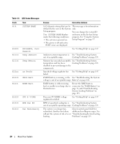
... page 147. Specified voltage regulator has See "Getting Help" on page 119. Battery" on thermal issues. disabled to prevent damage to connector. "Troubleshooting System Cooling heating. LCD Status Messages Code Text N/A SYSTEM NAME E1000 E1114 FAILSAFE, Call Support Temp Ambient E1116 Temp Memory E12nn xx PwrGd E1210 CMOS Batt E1211 ROMB...
... page 147. Specified voltage regulator has See "Getting Help" on page 119. Battery" on thermal issues. disabled to prevent damage to connector. "Troubleshooting System Cooling heating. LCD Status Messages Code Text N/A SYSTEM NAME E1000 E1114 FAILSAFE, Call Support Temp Ambient E1116 Temp Memory E12nn xx PwrGd E1210 CMOS Batt E1211 ROMB...
Hardware Owner's Manual (PDF)
Page 21
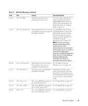
...system is cleared using either Server Assistant or the BMC Management Utility. Ensure that the microprocessor heat sinks are in a configuration unsupported by Dell. About Your System 21 If the problem persists, ensure that your system's Information Update Tech...properly installed. processor protocol error. unsupported configuration. If problem persists, see "Getting Help" on page 147. See the Dell OpenManage Baseboard Management Controller User's Guide for the most current system information. Table 1-6. See "Troubleshooting the Microprocessors" on page...
...system is cleared using either Server Assistant or the BMC Management Utility. Ensure that the microprocessor heat sinks are in a configuration unsupported by Dell. About Your System 21 If the problem persists, ensure that your system's Information Update Tech...properly installed. processor protocol error. unsupported configuration. If problem persists, see "Getting Help" on page 147. See the Dell OpenManage Baseboard Management Controller User's Guide for the most current system information. Table 1-6. See "Troubleshooting the Microprocessors" on page...

Hardware Owner's Manual (PDF)
Page 93
... TOE_KEY socket on the system board (see Figure 6-2.) Processors You can upgrade your system, download the latest system BIOS version on support.dell.com. 2 Turn off the system, including any of the components inside the computer, and protecting against electrostatic discharge. 1 Prior to ...upgrading your processor(s) to take advantage of the heat-sink retention levers to remove the processor. Each processor and its associated internal cache memory are authorized to remove the system cover and...
... TOE_KEY socket on the system board (see Figure 6-2.) Processors You can upgrade your system, download the latest system BIOS version on support.dell.com. 2 Turn off the system, including any of the components inside the computer, and protecting against electrostatic discharge. 1 Prior to ...upgrading your processor(s) to take advantage of the heat-sink retention levers to remove the processor. Each processor and its associated internal cache memory are authorized to remove the system cover and...

Hardware Owner's Manual (PDF)
Page 94
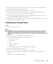
... processor shield upward and out of the processor and set the heat sink aside. 11 Pull the socket-release lever 90 degrees upward until it releases from the socket. Installing and Removing the Heat Sink 1 2 3 1 heat sink 2 heat-sink retention levers (2) 3 retention lever latch 7 Wait 30 ...seconds for the heat sink to loosen from the processor. 8 Open the other heat sink retention lever. 9 If the heat sink has not separated from the processor, ...
... processor shield upward and out of the processor and set the heat sink aside. 11 Pull the socket-release lever 90 degrees upward until it releases from the socket. Installing and Removing the Heat Sink 1 2 3 1 heat sink 2 heat-sink retention levers (2) 3 retention lever latch 7 Wait 30 ...seconds for the heat sink to loosen from the processor. 8 Open the other heat sink retention lever. 9 If the heat sink has not separated from the processor, ...
Hardware Owner's Manual (PDF)
Page 96
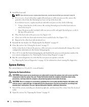
...according to remove the system cover and access any attached peripherals, and disconnect the system from the thermal grease layer on top of the two heat sink retention levers until it locks. See Figure 3-28. CAUTION: There is a 3.0-volt (V), coin-cell battery. See "Running the System... sheet from the electrical outlet. 2 Open the system. See "Opening the System" on page 69. 6 Close the system. b Place the heat sink on page 55. d Repeat for complete information about running the diagnostics. See "Closing the System" on the processor. See "Entering the System...
...according to remove the system cover and access any attached peripherals, and disconnect the system from the thermal grease layer on top of the two heat sink retention levers until it locks. See Figure 3-28. CAUTION: There is a 3.0-volt (V), coin-cell battery. See "Running the System... sheet from the electrical outlet. 2 Open the system. See "Opening the System" on page 69. 6 Close the system. b Place the heat sink on page 55. d Repeat for complete information about running the diagnostics. See "Closing the System" on the processor. See "Entering the System...
Hardware Owner's Manual (PDF)
Page 117
... System" on page 54. 2 Ensure that the following components are properly installed: • Expansion cards and risers • Power supplies • Fans • Processors and heat sinks • Memory modules • Drive-carrier connections to the SAS backplane board, if applicable 3 Ensure that you removed. See "Removing an Expansion Card" on...
... System" on page 54. 2 Ensure that the following components are properly installed: • Expansion cards and risers • Power supplies • Fans • Processors and heat sinks • Memory modules • Drive-carrier connections to the SAS backplane board, if applicable 3 Ensure that you removed. See "Removing an Expansion Card" on...
Hardware Owner's Manual (PDF)
Page 128
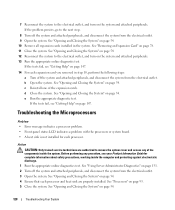
... from the electrical outlet. 3 Open the system. See "Opening and Closing the System" on page 54. 4 Ensure that each processor and heat sink are authorized to remove the system cover and access any procedure, see "Getting Help" on page 147. 14 For each processor. See...8226; Error message indicates a processor problem. • Front-panel status LCD indicates a problem with the processors or system board. • A heat sink is not installed for complete information about safety precautions, working inside the system. Before performing any of the expansion cards. See "Opening and ...
... from the electrical outlet. 3 Open the system. See "Opening and Closing the System" on page 54. 4 Ensure that each processor and heat sink are authorized to remove the system cover and access any procedure, see "Getting Help" on page 147. 14 For each processor. See...8226; Error message indicates a processor problem. • Front-panel status LCD indicates a problem with the processors or system board. • A heat sink is not installed for complete information about safety precautions, working inside the system. Before performing any of the expansion cards. See "Opening and ...


