Processor Upgrade Installation Guide
Page 5
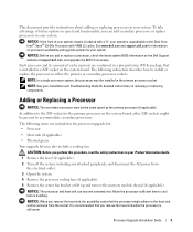
... and Troubleshooting Guide for the primary processor on removing or replacing components. Adding or Replacing a Processor NOTICE: The secondary processor must be the same speed as the primary processor (if applicable). Allow the processor sufficient time to install or replace the processor in a ZIF socket on the Dell Support website at support.dell.com, and upgrade the BIOS...
... and Troubleshooting Guide for the primary processor on removing or replacing components. Adding or Replacing a Processor NOTICE: The secondary processor must be the same speed as the primary processor (if applicable). Allow the processor sufficient time to install or replace the processor in a ZIF socket on the Dell Support website at support.dell.com, and upgrade the BIOS...
Processor Upgrade Installation Guide
Page 6
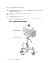
If you are upgrading an existing processor: a Press the tab on the end of one of the heat-sink retention levers to disengage the lever, then lift the lever 90 degrees. See ...Figure 1-1. b Press the tab on the end of one of the heat-sink retention levers to step 7. 6 If you are installing an additional processor: a Locate the secondary processor socket. c Repeat step b for the remaining heat-sink retention lever. Removing and Installing the Heat Sink heat sink (typical) heat-sink retention lever...
If you are upgrading an existing processor: a Press the tab on the end of one of the heat-sink retention levers to disengage the lever, then lift the lever 90 degrees. See ...Figure 1-1. b Press the tab on the end of one of the heat-sink retention levers to step 7. 6 If you are installing an additional processor: a Locate the secondary processor socket. c Repeat step b for the remaining heat-sink retention lever. Removing and Installing the Heat Sink heat sink (typical) heat-sink retention lever...
Processor Upgrade Installation Guide
Page 7
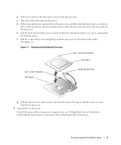
..., then counterclockwise, direction until the processor is ready for the new processor. 7 Unpack the new processor. Removing and Installing the Processor pin-1 corner of processor processor pin-1 corner of socket ZIF socket socket-release lever g Lift the processor out of the processor and set the heat sink upside down... Do not pry the heat sink off of the socket and leave the release lever up until it releases from the processor, carefully rotate the heat sink in your Installation and Troubleshooting Guide for instructions about obtaining technical assistance. See Figure 1-2. ...
..., then counterclockwise, direction until the processor is ready for the new processor. 7 Unpack the new processor. Removing and Installing the Processor pin-1 corner of processor processor pin-1 corner of socket ZIF socket socket-release lever g Lift the processor out of the processor and set the heat sink upside down... Do not pry the heat sink off of the socket and leave the release lever up until it releases from the processor, carefully rotate the heat sink in your Installation and Troubleshooting Guide for instructions about obtaining technical assistance. See Figure 1-2. ...
Processor Upgrade Installation Guide
Page 8
... socket. Place this corner in the same corner of the ZIF socket identified by locating the tiny gold triangle on the processor socket is misaligned. NOTE: Because the system uses a ZIF processor socket, do not use a clean lint-free cloth to bend the pins. NOTE: Use the heat sink that you... are installing an additional processor, locate the new heat sink in the processor upgrade kit. d Close one corner of the two heat-sink retention levers until it snaps into the socket with the correct ...
... socket. Place this corner in the same corner of the ZIF socket identified by locating the tiny gold triangle on the processor socket is misaligned. NOTE: Because the system uses a ZIF processor socket, do not use a clean lint-free cloth to bend the pins. NOTE: Use the heat sink that you... are installing an additional processor, locate the new heat sink in the processor upgrade kit. d Close one corner of the two heat-sink retention levers until it snaps into the socket with the correct ...
Processor Upgrade Installation Guide
Page 9
... System Diagnostics" in the System Setup program. 16 Press to enter the System Setup program, and check that the new processor operates correctly. Processor Upgrade Installation Guide 7 See your system and peripherals to their electrical outlets, and turn them on. 11 Reinstall the center...fan bracket or replace the memory module shroud (if applicable). 12 If you have added an additional processor, install the processor cooling fan(s) for the new processor. 13 Replace the processor cooling fans (if applicable). 14 Close the system. 15 Reconnect your User's Guide for information ...
... System Diagnostics" in the System Setup program. 16 Press to enter the System Setup program, and check that the new processor operates correctly. Processor Upgrade Installation Guide 7 See your system and peripherals to their electrical outlets, and turn them on. 11 Reinstall the center...fan bracket or replace the memory module shroud (if applicable). 12 If you have added an additional processor, install the processor cooling fan(s) for the new processor. 13 Replace the processor cooling fans (if applicable). 14 Close the system. 15 Reconnect your User's Guide for information ...

Processor Upgrade Installation Guide
Page 10
8 Processor Upgrade Installation Guide
8 Processor Upgrade Installation Guide
Updating Your NIC Teaming Drivers (.pdf)
Page 4
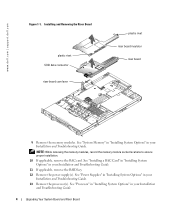
...dell.com | support.dell.com Figure 1-1. NOTE: While removing the memory modules, record the memory module socket locations to ensure proper installation. 10 If applicable, remove the RAC card. See "System Memory" in "Installing System Options" in your Installation and Troubleshooting Guide. See "Processor...power supply(s). See "Power Supplies" in "Installing System Options" in your Installation and Troubleshooting Guide. 13 Remove the processor(s). Installing and Removing the Riser Board plastic rivet SCSI data connector riser board cam lever plastic rivet riser board insulator ...
...dell.com | support.dell.com Figure 1-1. NOTE: While removing the memory modules, record the memory module socket locations to ensure proper installation. 10 If applicable, remove the RAC card. See "System Memory" in "Installing System Options" in your Installation and Troubleshooting Guide. See "Processor...power supply(s). See "Power Supplies" in "Installing System Options" in your Installation and Troubleshooting Guide. 13 Remove the processor(s). Installing and Removing the Riser Board plastic rivet SCSI data connector riser board cam lever plastic rivet riser board insulator ...
Updating Your NIC Teaming Drivers (.pdf)
Page 6
...If you are certain the riser board is correctly aligned with the system board, carefully close the cam lever to a vertical position. www.dell.com | support.dell.com 5 Replace the processor(s). 6 If applicable, replace the RAC card. 7 If applicable, replace the RAID key. 8 Replace the power supply(s). 9 Install the...outer edge of the riser board. • Align the connector on the underside of the riser board with the corresponding connector on support.dell.com. 13 Reinstall the cover. 14 If applicable, reattach the bezel. 6 Upgrading Your System Board and Riser Board See "SCSI Backplane ...
...If you are certain the riser board is correctly aligned with the system board, carefully close the cam lever to a vertical position. www.dell.com | support.dell.com 5 Replace the processor(s). 6 If applicable, replace the RAC card. 7 If applicable, replace the RAID key. 8 Replace the power supply(s). 9 Install the...outer edge of the riser board. • Align the connector on the underside of the riser board with the corresponding connector on support.dell.com. 13 Reinstall the cover. 14 If applicable, reattach the bezel. 6 Upgrading Your System Board and Riser Board See "SCSI Backplane ...
Updating Your NIC Teaming Drivers (.pdf)
Page 7
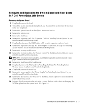
... and Troubleshooting Guide. See "Power Supplies" in "Installing System Options" in your Installation and Troubleshooting Guide. 15 Remove the processor(s). See "Processor" in "Installing System Options" in your Installation and Troubleshooting Guide. 9 Remove the memory module cover. 10 Remove the memory...Upgrading Your System Board and Riser Board 7 See Figure 1-3. Removing and Replacing the System Board and Riser Board In A Dell PowerEdge 2850 System Removing the System Board 1 If applicable, remove the bezel. 2 Turn off the system and attached peripherals, and disconnect...
... and Troubleshooting Guide. See "Power Supplies" in "Installing System Options" in your Installation and Troubleshooting Guide. 15 Remove the processor(s). See "Processor" in "Installing System Options" in your Installation and Troubleshooting Guide. 9 Remove the memory module cover. 10 Remove the memory...Upgrading Your System Board and Riser Board 7 See Figure 1-3. Removing and Replacing the System Board and Riser Board In A Dell PowerEdge 2850 System Removing the System Board 1 If applicable, remove the bezel. 2 Turn off the system and attached peripherals, and disconnect...
Updating Your NIC Teaming Drivers (.pdf)
Page 9
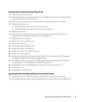
... Reinstall the cover. 18 If applicable, reattach the bezel. See Figure 1-3. 7 Replace the memory modules. 8 Replace the memory module cover. 9 Replace the processor(s). 10 If applicable, replace the RAC card. 11 If applicable, replace the RAID key. 12 Replace the back-fan tray and the back fans. 13 ...the retention pin engages. 4 Replace the front-fan tray: a Place the front-fan tray over the three securing posts. See "Upgrading the Dell PowerEdge 2850 Expansion-Card Riser Board." 15 Reinstall the expansion-card-cage. See Figure 1-4. b Slide the front-fan tray to the riser board. Upgrading the...
... Reinstall the cover. 18 If applicable, reattach the bezel. See Figure 1-3. 7 Replace the memory modules. 8 Replace the memory module cover. 9 Replace the processor(s). 10 If applicable, replace the RAC card. 11 If applicable, replace the RAID key. 12 Replace the back-fan tray and the back fans. 13 ...the retention pin engages. 4 Replace the front-fan tray: a Place the front-fan tray over the three securing posts. See "Upgrading the Dell PowerEdge 2850 Expansion-Card Riser Board." 15 Reinstall the expansion-card-cage. See Figure 1-4. b Slide the front-fan tray to the riser board. Upgrading the...


