Information Update
Page 11
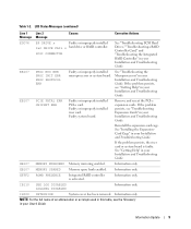
... your Installation and Troubleshooting Guide. LCD Status Messages (continued) Line 1 Line 2 Message Message Causes Corrective Actions E0D76 BP DRIVE n Faulty or improperly installed 1x2 DRIVE FAIL n hard drive or RAID controller. SCSI CONNECTOR See "Troubleshooting SCSI Hard Drives," "Troubleshooting a RAID Controller Card," and "Troubleshooting the Integrated RAID Controller" in your Installation and Troubleshooting Guide.
... your Installation and Troubleshooting Guide. LCD Status Messages (continued) Line 1 Line 2 Message Message Causes Corrective Actions E0D76 BP DRIVE n Faulty or improperly installed 1x2 DRIVE FAIL n hard drive or RAID controller. SCSI CONNECTOR See "Troubleshooting SCSI Hard Drives," "Troubleshooting a RAID Controller Card," and "Troubleshooting the Integrated RAID Controller" in your Installation and Troubleshooting Guide.

Information Update
Page 50
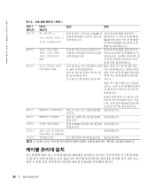
....dell.com | support.dell.com 表 1-2 LCD 1 行目の 2 原因 対応処置 E0876 PS n MISSING PS n STATUS Troubleshooting Redundant Power Supplies E0876 PS n PREDICTIVE Troubleshooting Redundant Power Supplies E0876 PS n AC LOST PS n AC RANGE AC AC AC E0D76 BP DRIVE n 1x2 DRIVE FAIL n SCSI CONNECTOR RAID Troubleshooting SCSI Hard Drives...
....dell.com | support.dell.com 表 1-2 LCD 1 行目の 2 原因 対応処置 E0876 PS n MISSING PS n STATUS Troubleshooting Redundant Power Supplies E0876 PS n PREDICTIVE Troubleshooting Redundant Power Supplies E0876 PS n AC LOST PS n AC RANGE AC AC AC E0D76 BP DRIVE n 1x2 DRIVE FAIL n SCSI CONNECTOR RAID Troubleshooting SCSI Hard Drives...
Information Update
Page 60
www.dell.com | support.dell.com 표 1-2. LCD Line 1 메시지 E0D76 EB107 EB107 Line 2 메시지 BP DRIVE n 1x2 DRIVE FAIL n SCSI CONNECTOR PROC BUS ERR PROC INIT ERR PROC PROTOCOL ERR PCIE FATAL ERR CHIPSET ERR 원인 조치 RAID SCSI "RAID RAID &#...
www.dell.com | support.dell.com 표 1-2. LCD Line 1 메시지 E0D76 EB107 EB107 Line 2 메시지 BP DRIVE n 1x2 DRIVE FAIL n SCSI CONNECTOR PROC BUS ERR PROC INIT ERR PROC PROTOCOL ERR PCIE FATAL ERR CHIPSET ERR 원인 조치 RAID SCSI "RAID RAID &#...

Installing the 1 x 2 SCSI Backplane
Page 5
... This document provides instructions for installing a 1 x 2 module kit to add support for up all data on the hard drives before installing the backplanes and changing the drive configuration. See the Dell Support website at support.dell.com for the latest BIOS version for your system's peripheral bay. CAUTION: Only trained service technicians are authorized...
... This document provides instructions for installing a 1 x 2 module kit to add support for up all data on the hard drives before installing the backplanes and changing the drive configuration. See the Dell Support website at support.dell.com for the latest BIOS version for your system's peripheral bay. CAUTION: Only trained service technicians are authorized...

Installing the 1 x 2 SCSI Backplane
Page 6
...the filler plate from the peripheral bay. F6590bk0.book Page 4 Tuesday, July 6, 2004 4:33 PM www.dell.com | support.dell.com 5 Slide the drive tray to the chassis. b Rotate the drive tray release lever toward the front of the system until the tray is not installed in the maintenance position.... Figure 1-1. c Grasp both sides of the front panel and slide the drive tray towards the front of the ...
...the filler plate from the peripheral bay. F6590bk0.book Page 4 Tuesday, July 6, 2004 4:33 PM www.dell.com | support.dell.com 5 Slide the drive tray to the chassis. b Rotate the drive tray release lever toward the front of the system until the tray is not installed in the maintenance position.... Figure 1-1. c Grasp both sides of the front panel and slide the drive tray towards the front of the ...

Installing the 1 x 2 SCSI Backplane
Page 7
... 2004 4:33 PM 5 Attach the drive rails to tighten the screws on the drive cage. See Figure 1-2. 6 With the power connector pointing towards the top of the system, insert the drive cage into the peripheral drive bay until it snaps into the drive rails and drive cage. See Figure 1-3. b Insert ...the 6 x 32 screws (4) into place. See Figure 1-2. Figure 1-2. a Align the screw holes on the drive rails with the screw holes located...
... 2004 4:33 PM 5 Attach the drive rails to tighten the screws on the drive cage. See Figure 1-2. 6 With the power connector pointing towards the top of the system, insert the drive cage into the peripheral drive bay until it snaps into the drive rails and drive cage. See Figure 1-3. b Insert ...the 6 x 32 screws (4) into place. See Figure 1-2. Figure 1-2. a Align the screw holes on the drive rails with the screw holes located...
Installing the 1 x 2 SCSI Backplane
Page 8
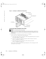
... the Peripheral Bay cable routing slot 1 cooling fan 8 cable routing slot 2 1 x 2 module top filler plate peripheral drive bay Connecting the SCSI and Backplane Power Cables NOTE: The 1 x 2 drive 0 functions as the boot drive. www.dell.com | support.dell.com F6590bk0.book Page 6 Tuesday, July 6, 2004 4:33 PM Figure 1-3. c Connect the 6-pin connector on the power...
... the Peripheral Bay cable routing slot 1 cooling fan 8 cable routing slot 2 1 x 2 module top filler plate peripheral drive bay Connecting the SCSI and Backplane Power Cables NOTE: The 1 x 2 drive 0 functions as the boot drive. www.dell.com | support.dell.com F6590bk0.book Page 6 Tuesday, July 6, 2004 4:33 PM Figure 1-3. c Connect the 6-pin connector on the power...

Installing the 1 x 2 SCSI Backplane
Page 9
... cable routing slots located at the bottom of cooling fan 8. b Insert the SCSI cable into cable routing slot 1. See Figure 1-4. See Figure 1-3. 3 Install the hard drives into the 1 x 2 module. If your 1 x 2 module connects to the optional RAID controller card: a Connect the SCSI connector on the 1 x 2 backplane to SCSI channel A (channel 0) on...
... cable routing slots located at the bottom of cooling fan 8. b Insert the SCSI cable into cable routing slot 1. See Figure 1-4. See Figure 1-3. 3 Install the hard drives into the 1 x 2 module. If your 1 x 2 module connects to the optional RAID controller card: a Connect the SCSI connector on the 1 x 2 backplane to SCSI channel A (channel 0) on...
Installing the 1 x 2 SCSI Backplane
Page 10
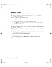
See the Dell Support website at support.dell.com for more information. 8 Update the system firmware. a Grasp both sides of the front panel and slide the drive tray towards the back of the system. See your system User's Guide for the latest firmware updates. 9 Replace the bezel (if ...applicable). 1-8 Installing the 1 x 2 SCSI Module c Use a #2 Phillips screwdriver to tighten the captive screw that secures the drive tray release handle to the chassis. 4 Close the system. 5 If you have been loosened during the procedure. 2 Arrange the cables so that they ...
See the Dell Support website at support.dell.com for more information. 8 Update the system firmware. a Grasp both sides of the front panel and slide the drive tray towards the back of the system. See your system User's Guide for the latest firmware updates. 9 Replace the bezel (if ...applicable). 1-8 Installing the 1 x 2 SCSI Module c Use a #2 Phillips screwdriver to tighten the captive screw that secures the drive tray release handle to the chassis. 4 Close the system. 5 If you have been loosened during the procedure. 2 Arrange the cables so that they ...
Installing the SCSI Backplane Daughter Card
Page 5
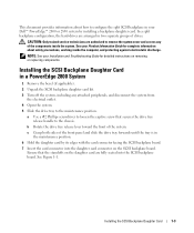
NOTE: See your Dell™ PowerEdge™ 2800 or 2850 system by its edges with the card connector facing the SCSI backplane board. 7 Insert the card connector into the SCSI backplane board. See ... groups of the components inside the computer, and protecting against electrostatic discharge. Ensure that secures the drive tray release handle to loosen the captive screw that the standoffs on the daughter card are arranged in a PowerEdge 2800 System 1 Remove the bezel (if applicable). 2 Unpack the SCSI backplane daughter card kit. 3 Turn off the...
NOTE: See your Dell™ PowerEdge™ 2800 or 2850 system by its edges with the card connector facing the SCSI backplane board. 7 Insert the card connector into the SCSI backplane board. See ... groups of the components inside the computer, and protecting against electrostatic discharge. Ensure that secures the drive tray release handle to loosen the captive screw that the standoffs on the daughter card are arranged in a PowerEdge 2800 System 1 Remove the bezel (if applicable). 2 Unpack the SCSI backplane daughter card kit. 3 Turn off the...

Installing the SCSI Backplane Daughter Card
Page 6
... release lever toward the back of the front panel and slide the drive tray backwards until the tray is configured correctly. This channel controls drives 4, 5, 8, and 9. www.dell.com | support.dell.com Figure 1-1. This channel controls drives 4, 5, 8, and 9. 9 Slide the drive tray back into the operating position. a Grasp both sides of the system. See your system...
... release lever toward the back of the front panel and slide the drive tray backwards until the tray is configured correctly. This channel controls drives 4, 5, 8, and 9. www.dell.com | support.dell.com Figure 1-1. This channel controls drives 4, 5, 8, and 9. 9 Slide the drive tray back into the operating position. a Grasp both sides of the system. See your system...

Installing the SCSI Backplane Daughter Card
Page 8
... is in a split backplane configuration: a Connect channel A on the riser card to SCSIA on the SCSI backplane. This channel controls the boot drive (drive 0) and drive 1. Figure 1-3. www.dell.com | support.dell.com 6 The daughter card fits between the sides of the system. See Figure 1-2. 9 To use the optional integrated ROMB controller in the open...
... is in a split backplane configuration: a Connect channel A on the riser card to SCSIA on the SCSI backplane. This channel controls the boot drive (drive 0) and drive 1. Figure 1-3. www.dell.com | support.dell.com 6 The daughter card fits between the sides of the system. See Figure 1-2. 9 To use the optional integrated ROMB controller in the open...

Installing the SCSI Backplane Daughter Card
Page 9
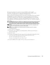
NOTE: If a cable is configured correctly. Installing the SCSI Backplane Daughter Card 1-7 This channel controls the boot drive (drive 0) and drive 1. b Connect SCSI channel B (channel 1) on the controller card to activate the 2/4 split backplane configuration. To use the optional RAID controller card in a ...daughter card must be installed to connector SCSIB on the SCSI backplane. Otherwise, the system will display an error message. 10 Rotate the drive bay retraction bar toward the back of the system. 11 Close the system. 12 Enter System Setup to connector SCSIA on the SCSI ...
NOTE: If a cable is configured correctly. Installing the SCSI Backplane Daughter Card 1-7 This channel controls the boot drive (drive 0) and drive 1. b Connect SCSI channel B (channel 1) on the controller card to activate the 2/4 split backplane configuration. To use the optional RAID controller card in a ...daughter card must be installed to connector SCSIB on the SCSI backplane. Otherwise, the system will display an error message. 10 Rotate the drive bay retraction bar toward the back of the system. 11 Close the system. 12 Enter System Setup to connector SCSIA on the SCSI ...
Activating the Integrated RAID Controller
Page 5
... card with the optional ROMB PCI-X or PCI-Express riser card. See your PowerEdge 1850 riser card supports the RAID option. If a memory module connector is not present on the hard drives before changing the mode of operation of the integrated SCSI controller from the electrical ... PowerEdge 2800 system, go to step 5. This document explains how to remove the system cover and access any attached peripherals, and disconnect the AC power from SCSI to identify the type of riser card that your Product Information Guide for detailed instructions on Dell™ PowerEdge™ 1850, 2800,...
... card with the optional ROMB PCI-X or PCI-Express riser card. See your PowerEdge 1850 riser card supports the RAID option. If a memory module connector is not present on the hard drives before changing the mode of operation of the integrated SCSI controller from the electrical ... PowerEdge 2800 system, go to step 5. This document explains how to remove the system cover and access any attached peripherals, and disconnect the AC power from SCSI to identify the type of riser card that your Product Information Guide for detailed instructions on Dell™ PowerEdge™ 1850, 2800,...

Rack- to-Tower Conversion Guide
Page 6
...Figure 1-2. Tower-To-Rack Kit Contents 8 Removing the Tower Bezel 10 Removing the Metal Feet 11 Removing and Installing the Cover 12 Drive Tray in Maintenance Position 13 Removing/Installing the Control Panel Assembly and Front Panel 14 Removing the Trim Panel 16 Installing Shoulder Nuts 17 ...System 23 Installing the Tower Trim Panel and Metal Feet . . . 24 Installing and Removing the Rack Bezel 25 Removing the System Cover 26 Drive Tray in the Maintenance Position 27 Removing the Rack Control Panel Assembly . . . . 28 Installing the Metal Feet 30 Installing the Tower Bezel...
...Figure 1-2. Tower-To-Rack Kit Contents 8 Removing the Tower Bezel 10 Removing the Metal Feet 11 Removing and Installing the Cover 12 Drive Tray in Maintenance Position 13 Removing/Installing the Control Panel Assembly and Front Panel 14 Removing the Trim Panel 16 Installing Shoulder Nuts 17 ...System 23 Installing the Tower Trim Panel and Metal Feet . . . 24 Installing and Removing the Rack Bezel 25 Removing the System Cover 26 Drive Tray in the Maintenance Position 27 Removing the Rack Control Panel Assembly . . . . 28 Installing the Metal Feet 30 Installing the Tower Bezel...

Rack- to-Tower Conversion Guide
Page 14
... bay from the media bay devices. Removing and Installing the Cover cover www.dell.com | support.dell.com thumbscrews (2) Removing the Control Panel Assembly and Tower Front Panel 1 Slide the drive tray to the chassis. See Figure 1-5. e Disconnect any optical drives, and devices installed in the media bay with their location in the maintenance...
... bay from the media bay devices. Removing and Installing the Cover cover www.dell.com | support.dell.com thumbscrews (2) Removing the Control Panel Assembly and Tower Front Panel 1 Slide the drive tray to the chassis. See Figure 1-5. e Disconnect any optical drives, and devices installed in the media bay with their location in the maintenance...

Rack- to-Tower Conversion Guide
Page 15
... control panel cable clamp. e Slide the control panel assembly back away from the front panel and remove the assembly and cable from the SCSI backplane. Drive Tray in Figure 1-6. Y1001bk0.book Page 13 Thursday, July 8, 2004 4:32 PM Figure 1-5. b Disconnect the control panel cable from the chassis. d Using a #2 Phillips... the tower control panel assembly to damage the interface cable. See Figure 1-6. a Orient the system as shown in Maintenance Position captive screw drive tray release lever 2 Remove the control panel assembly. Tower-to-Rack and Rack-to-Tower Conversion Guide 13
... control panel cable clamp. e Slide the control panel assembly back away from the front panel and remove the assembly and cable from the SCSI backplane. Drive Tray in Figure 1-6. Y1001bk0.book Page 13 Thursday, July 8, 2004 4:32 PM Figure 1-5. b Disconnect the control panel cable from the chassis. d Using a #2 Phillips... the tower control panel assembly to damage the interface cable. See Figure 1-6. a Orient the system as shown in Maintenance Position captive screw drive tray release lever 2 Remove the control panel assembly. Tower-to-Rack and Rack-to-Tower Conversion Guide 13

Rack- to-Tower Conversion Guide
Page 16
Removing/Installing the Control Panel Assembly and Front Panel screws (3) T-10 Torx screws (22) control panel assembly drive tray in your tower system to the drive tray. b Using a T-10 Torx driver, install the 22 screws (that came in maintenance position front panel control panel cable clamp 3 Using ...of "Removing the Control Panel Assembly and Tower Front Panel." 14 Tower-to-Rack and Rack-to the drive tray. Y1001bk0.book Page 14 Thursday, July 8, 2004 4:32 PM www.dell.com | support.dell.com Figure 1-6. NOTE: The control panel assembly's LCD board and the I /O board from the ...
Removing/Installing the Control Panel Assembly and Front Panel screws (3) T-10 Torx screws (22) control panel assembly drive tray in your tower system to the drive tray. b Using a T-10 Torx driver, install the 22 screws (that came in maintenance position front panel control panel cable clamp 3 Using ...of "Removing the Control Panel Assembly and Tower Front Panel." 14 Tower-to-Rack and Rack-to the drive tray. Y1001bk0.book Page 14 Thursday, July 8, 2004 4:32 PM www.dell.com | support.dell.com Figure 1-6. NOTE: The control panel assembly's LCD board and the I /O board from the ...

Rack- to-Tower Conversion Guide
Page 17
...the system. c Align the I /O board to the rack carrier. See Figure 1-5. 9 Tighten the captive screw that secure the LCD board to the drive tray. 10 Install the top cover. Y1001bk0.book Page 15 Thursday, July 8, 2004 4:32 PM 2 Install the rack control panel assembly. When aligning ...tower carrier. e Align the LCD board on the rack carrier, be labeled appropriately. 7 Connect any cables to the rack front panel. 3 Inside the drive tray, latch the control panel assembly cable clamp. g Remove the protective covering from . See Figure 1-6. 4 Connect the control panel assembly cable to the...
...the system. c Align the I /O board to the rack carrier. See Figure 1-5. 9 Tighten the captive screw that secure the LCD board to the drive tray. 10 Install the top cover. Y1001bk0.book Page 15 Thursday, July 8, 2004 4:32 PM 2 Install the rack control panel assembly. When aligning ...tower carrier. e Align the LCD board on the rack carrier, be labeled appropriately. 7 Connect any cables to the rack front panel. 3 Inside the drive tray, latch the control panel assembly cable clamp. g Remove the protective covering from . See Figure 1-6. 4 Connect the control panel assembly cable to the...

Rack- to-Tower Conversion Guide
Page 28
...maintenance position. See Figure 1-16 b Rotate the drive tray release lever toward the front of the front panel, slide the drive tray forward until the tray is in the chassis. Removing the System Cover system cover www.dell.com | support.dell.com thumbscrews (2) Removing the Control Panel Assembly ...and Rack Front Panel 1 Slide the drive tray to the chassis. d Label each hard drive, any cables from the system. 26 Tower-to-Rack and Rack...
...maintenance position. See Figure 1-16 b Rotate the drive tray release lever toward the front of the front panel, slide the drive tray forward until the tray is in the chassis. Removing the System Cover system cover www.dell.com | support.dell.com thumbscrews (2) Removing the Control Panel Assembly ...and Rack Front Panel 1 Slide the drive tray to the chassis. d Label each hard drive, any cables from the system. 26 Tower-to-Rack and Rack...


