
Processor Upgrade Installation Guide (.pdf)
Page 1
www.dell.com | support.dell.com About Cautions CAUTION: A CAUTION indicates a potential for installing the remote access card on removing or replacing components. 1 Turn off the system, including any of ... document provides instructions for property damage, personal injury, or death. See Figure 1. 4 Remove the memory cooling shroud (if present). 5 Remove the memory module fans at the back of the system (if present). 6 Remove the fan bracket at the back of the components inside the computer, and protecting against electrostatic discharge. July 2004
www.dell.com | support.dell.com About Cautions CAUTION: A CAUTION indicates a potential for installing the remote access card on removing or replacing components. 1 Turn off the system, including any of ... document provides instructions for property damage, personal injury, or death. See Figure 1. 4 Remove the memory cooling shroud (if present). 5 Remove the memory module fans at the back of the system (if present). 6 Remove the fan bracket at the back of the components inside the computer, and protecting against electrostatic discharge. July 2004
Processor Upgrade Installation Guide (.pdf)
Page 2
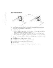
... on the system board, until the clips on the plastic standoffs snap over the card edge. 10 Reinstall the back fan bracket (if removed in step 6). 11 Reinstall the two memory module fans (if removed in step 5). 12 Reinstall the memory cooling shroud (if removed in the corners of the card aligned...
... on the system board, until the clips on the plastic standoffs snap over the card edge. 10 Reinstall the back fan bracket (if removed in step 6). 11 Reinstall the two memory module fans (if removed in step 5). 12 Reinstall the memory cooling shroud (if removed in the corners of the card aligned...

Information Update
Page 9
.... VOLT RISER 5V VOLT RISER Riser card voltage is out of three error messages can display sequentially on the events. Information Update 7 RPM FAN n FAN REDUNDANCY LOST Specified cooling fan is faulty, improperly installed, or missing. Table 1-2. See "Troubleshooting Redundant Power Supplies" in your Installation and Troubleshooting Guide. A maximum of acceptable range. See...
.... VOLT RISER 5V VOLT RISER Riser card voltage is out of three error messages can display sequentially on the events. Information Update 7 RPM FAN n FAN REDUNDANCY LOST Specified cooling fan is faulty, improperly installed, or missing. Table 1-2. See "Troubleshooting Redundant Power Supplies" in your Installation and Troubleshooting Guide. A maximum of acceptable range. See...
Installing the 1 x 2 SCSI Backplane
Page 8
www.dell.com | support.dell.com F6590bk0.book Page 6 Tuesday, July 6, 2004 4:33 PM Figure 1-3. NOTE: If your system is already configured with a tape backup unit: a Connect the 14-pin ..., use the existing power cable and complete step b and step c. 1-6 Installing the 1 x 2 SCSI Module Installing the 1 x 2 Module Into the Peripheral Bay cable routing slot 1 cooling fan 8 cable routing slot 2 1 x 2 module top filler plate peripheral drive bay Connecting the SCSI and Backplane Power Cables NOTE: The 1 x 2 drive 0 functions as the boot drive...
www.dell.com | support.dell.com F6590bk0.book Page 6 Tuesday, July 6, 2004 4:33 PM Figure 1-3. NOTE: If your system is already configured with a tape backup unit: a Connect the 14-pin ..., use the existing power cable and complete step b and step c. 1-6 Installing the 1 x 2 SCSI Module Installing the 1 x 2 Module Into the Peripheral Bay cable routing slot 1 cooling fan 8 cable routing slot 2 1 x 2 module top filler plate peripheral drive bay Connecting the SCSI and Backplane Power Cables NOTE: The 1 x 2 drive 0 functions as the boot drive...

Installing the 1 x 2 SCSI Backplane
Page 9
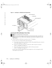
b Insert the SCSI cable harness into cable routing slot 2 and the cable routing slots located at the bottom of cooling fan 8. Figure 1-4. 1 x 2 Module and SCSI Backplane Connectors power connector 1 x 2 module peripheral bay power connector SCSI backplane 6-pin connector SCSI connector Installing the 1 x 2 SCSI Module 1-7 If your 1 x 2 ...
b Insert the SCSI cable harness into cable routing slot 2 and the cable routing slots located at the bottom of cooling fan 8. Figure 1-4. 1 x 2 Module and SCSI Backplane Connectors power connector 1 x 2 module peripheral bay power connector SCSI backplane 6-pin connector SCSI connector Installing the 1 x 2 SCSI Module 1-7 If your 1 x 2 ...
Installing the 1 x 2 SCSI Backplane
Page 10
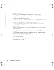
...tray release lever toward the back of the system until the tray is configured correctly. See the Dell Support website at support.dell.com for more information. 8 Update the system firmware. www.dell.com | support.dell.com F6590bk0.book Page 8 Tuesday, July 6, 2004 4:33 PM Completing the Installation 1 Check... (if applicable). 6 Reconnect the system to its electrical outlet and turn the system on the system cover or block the airflow of the fans or the cooling vents. 3 Slide the drive tray to the operating position. See your system User's Guide for the latest firmware updates. ...
...tray release lever toward the back of the system until the tray is configured correctly. See the Dell Support website at support.dell.com for more information. 8 Update the system firmware. www.dell.com | support.dell.com F6590bk0.book Page 8 Tuesday, July 6, 2004 4:33 PM Completing the Installation 1 Check... (if applicable). 6 Reconnect the system to its electrical outlet and turn the system on the system cover or block the airflow of the fans or the cooling vents. 3 Slide the drive tray to the operating position. See your system User's Guide for the latest firmware updates. ...
Processor Upgrade Installation Guide
Page 5
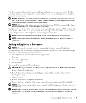
... in the processor upgrade kit: • Processor • Heat sink (if applicable) • Thermal grease Your upgrade kit may also include a cooling fan. This document provides instructions about adding or replacing processors in your system. NOTICE: If the front of future options in speed and functionality, you perform... are included in the primary processor socket. To take advantage of your system chassis is labeled with a "II," your system. See www.dell.com and support.dell.com for information on processor availability and upgrade options for detailed instructions on the...
... in the processor upgrade kit: • Processor • Heat sink (if applicable) • Thermal grease Your upgrade kit may also include a cooling fan. This document provides instructions about adding or replacing processors in your system. NOTICE: If the front of future options in speed and functionality, you perform... are included in the primary processor socket. To take advantage of your system chassis is labeled with a "II," your system. See www.dell.com and support.dell.com for information on processor availability and upgrade options for detailed instructions on the...
Processor Upgrade Installation Guide
Page 9
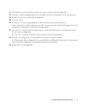
... replace the memory module shroud (if applicable). 12 If you have added an additional processor, install the processor cooling fan(s) for information about using the System Setup program. 17 Run the system diagnostics to verify that the processor information matches... and automatically changes the system configuration information in your Installation and Troubleshooting Guide for the new processor. 13 Replace the processor cooling fans (if applicable). 14 Close the system. 15 Reconnect your User's Guide for instructions about running the diagnostics and troubleshooting processor problems...
... replace the memory module shroud (if applicable). 12 If you have added an additional processor, install the processor cooling fan(s) for information about using the System Setup program. 17 Run the system diagnostics to verify that the processor information matches... and automatically changes the system configuration information in your Installation and Troubleshooting Guide for the new processor. 13 Replace the processor cooling fans (if applicable). 14 Close the system. 15 Reconnect your User's Guide for instructions about running the diagnostics and troubleshooting processor problems...


