
Processor Upgrade Installation Guide (.pdf)
Page 1
...2004 See Figure 1. 4 Remove the memory cooling shroud (if present). 5 Remove the memory module fans at the back of the system (if present). 6 Remove the fan bracket at the back of the components inside the computer, and protecting against electrostatic discharge. See your...3 Remove the filler plug from the system back panel. This document provides instructions for property damage, personal injury, or death. www.dell.com | support.dell.com About Cautions CAUTION: A CAUTION indicates a potential for installing the remote access card on removing or replacing components. 1 Turn off ...
...2004 See Figure 1. 4 Remove the memory cooling shroud (if present). 5 Remove the memory module fans at the back of the system (if present). 6 Remove the fan bracket at the back of the components inside the computer, and protecting against electrostatic discharge. See your...3 Remove the filler plug from the system back panel. This document provides instructions for property damage, personal injury, or death. www.dell.com | support.dell.com About Cautions CAUTION: A CAUTION indicates a potential for installing the remote access card on removing or replacing components. 1 Turn off ...
Processor Upgrade Installation Guide (.pdf)
Page 2
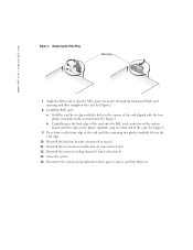
... connector on the system board, until the remaining two plastic standoffs fit over the card edge. 10 Reinstall the back fan bracket (if removed in step 6). 11 Reinstall the two memory module fans (if removed in step 5). 12 Reinstall the memory cooling shroud (if removed in step 4). 13 Close the system. 14... straighten the card. See Figure 2. 8 Install the RAC card: a Hold the card by its edges with the four plastic standoffs on the system board. www.dell.com | support.dell.com Figure 1.
... connector on the system board, until the remaining two plastic standoffs fit over the card edge. 10 Reinstall the back fan bracket (if removed in step 6). 11 Reinstall the two memory module fans (if removed in step 5). 12 Reinstall the memory cooling shroud (if removed in step 4). 13 Close the system. 14... straighten the card. See Figure 2. 8 Install the RAC card: a Hold the card by its edges with the four plastic standoffs on the system board. www.dell.com | support.dell.com Figure 1.

Information Update
Page 9
... and Troubleshooting Guide. Replace the RAID battery. Replace the system battery. See "Installing the ExpansionCard Cage" in your Installation and Troubleshooting Guide. RPM FAN n FAN REDUNDANCY LOST Specified cooling fan is out of acceptable range. Check the SEL for details on the LCD. TEMP RISER Riser card is out of three error messages...
... and Troubleshooting Guide. Replace the RAID battery. Replace the system battery. See "Installing the ExpansionCard Cage" in your Installation and Troubleshooting Guide. RPM FAN n FAN REDUNDANCY LOST Specified cooling fan is out of acceptable range. Check the SEL for details on the LCD. TEMP RISER Riser card is out of three error messages...
Installing the 1 x 2 SCSI Backplane
Page 8
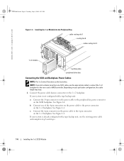
...a tape backup unit, use the appropriate cable to connect the 1 x 2 backplane to the power connector on the 1 x 2 backplane. www.dell.com | support.dell.com F6590bk0.book Page 6 Tuesday, July 6, 2004 4:33 PM Figure 1-3. See Figure 1-4. If your kit contains more than one of the 4-pin...to the peripheral bay power connector on the 1 x 2 backplane. See Figure 1-4. Installing the 1 x 2 Module Into the Peripheral Bay cable routing slot 1 cooling fan 8 cable routing slot 2 1 x 2 module top filler plate peripheral drive bay Connecting the SCSI and Backplane Power Cables NOTE: The 1 x 2 drive 0 ...
...a tape backup unit, use the appropriate cable to connect the 1 x 2 backplane to the power connector on the 1 x 2 backplane. www.dell.com | support.dell.com F6590bk0.book Page 6 Tuesday, July 6, 2004 4:33 PM Figure 1-3. See Figure 1-4. If your kit contains more than one of the 4-pin...to the peripheral bay power connector on the 1 x 2 backplane. See Figure 1-4. Installing the 1 x 2 Module Into the Peripheral Bay cable routing slot 1 cooling fan 8 cable routing slot 2 1 x 2 module top filler plate peripheral drive bay Connecting the SCSI and Backplane Power Cables NOTE: The 1 x 2 drive 0 ...

Installing the 1 x 2 SCSI Backplane
Page 9
See Figure 1-3. 3 Install the hard drives into cable routing slot 2 and the cable routing slots located at the bottom of cooling fan 8. If your 1 x 2 module connects to the optional RAID controller card: a Connect the SCSI connector on the 1 x 2 backplane to SCSI channel A (channel 0) on the riser card. ...
See Figure 1-3. 3 Install the hard drives into cable routing slot 2 and the cable routing slots located at the bottom of cooling fan 8. If your 1 x 2 module connects to the optional RAID controller card: a Connect the SCSI connector on the 1 x 2 backplane to SCSI channel A (channel 0) on the riser card. ...
Installing the 1 x 2 SCSI Backplane
Page 10
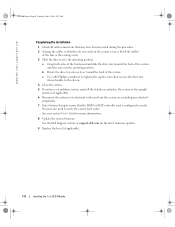
...the system on the system cover or block the airflow of the system. b Rotate the drive tray release lever toward the back of the fans or the cooling vents. 3 Slide the drive tray to the operating position. You may have a standalone system, reinstall the stabilizers and ...7 Enter System Setup to ensure that the RAID or SCSI controller card is configured correctly. See the Dell Support website at support.dell.com for more information. 8 Update the system firmware. www.dell.com | support.dell.com F6590bk0.book Page 8 Tuesday, July 6, 2004 4:33 PM Completing the Installation 1 Check all...
...the system on the system cover or block the airflow of the system. b Rotate the drive tray release lever toward the back of the fans or the cooling vents. 3 Slide the drive tray to the operating position. You may have a standalone system, reinstall the stabilizers and ...7 Enter System Setup to ensure that the RAID or SCSI controller card is configured correctly. See the Dell Support website at support.dell.com for more information. 8 Update the system firmware. www.dell.com | support.dell.com F6590bk0.book Page 8 Tuesday, July 6, 2004 4:33 PM Completing the Installation 1 Check all...
Processor Upgrade Installation Guide
Page 5
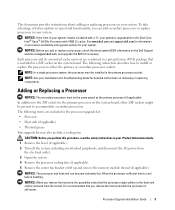
... or replacing components. To take advantage of your system chassis is labeled with 4 MB L2 cache. See www.dell.com and support.dell.com for information on processor availability and upgrade options for your system. NOTICE: When you can become extremely hot.... The following items are contained in a pin-grid array (PGA) package that the processor might be removed from the electrical outlet. 3 Open the system. 4 Remove the processor cooling fans...
... or replacing components. To take advantage of your system chassis is labeled with 4 MB L2 cache. See www.dell.com and support.dell.com for information on processor availability and upgrade options for your system. NOTICE: When you can become extremely hot.... The following items are contained in a pin-grid array (PGA) package that the processor might be removed from the electrical outlet. 3 Open the system. 4 Remove the processor cooling fans...
Processor Upgrade Installation Guide
Page 9
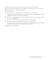
... the diagnostics and troubleshooting processor problems. 18 Replace the bezel (if applicable). Processor Upgrade Installation Guide 7 11 Reinstall the center fan bracket or replace the memory module shroud (if applicable). 12 If you have added an additional processor, install the processor cooling... fan(s) for the new processor. 13 Replace the processor cooling fans (if applicable). 14 Close the system. 15 Reconnect your system and peripherals to enter the System Setup program,...
... the diagnostics and troubleshooting processor problems. 18 Replace the bezel (if applicable). Processor Upgrade Installation Guide 7 11 Reinstall the center fan bracket or replace the memory module shroud (if applicable). 12 If you have added an additional processor, install the processor cooling... fan(s) for the new processor. 13 Replace the processor cooling fans (if applicable). 14 Close the system. 15 Reconnect your system and peripherals to enter the System Setup program,...


