Activating the Dell PERC2
Page 3
... the ejectors on the RAID controller DIMM socket (see Figure 1-2). Dell PowerEdge 2400 Systems-Activating the Dell PowerEdge Expandable RAID Controller 2/Si 1-1 Remove the cooling shroud. To activate the integrated PowerEdge Expandable RAID Controller (PERC) 2/Si, perform the following steps. 1. Turn off and unplug your system Installation and Troubleshooting Guide for more information. 3. Remove the right-side...
... the ejectors on the RAID controller DIMM socket (see Figure 1-2). Dell PowerEdge 2400 Systems-Activating the Dell PowerEdge Expandable RAID Controller 2/Si 1-1 Remove the cooling shroud. To activate the integrated PowerEdge Expandable RAID Controller (PERC) 2/Si, perform the following steps. 1. Turn off and unplug your system Installation and Troubleshooting Guide for more information. 3. Remove the right-side...
Activating the Dell PERC2
Page 5
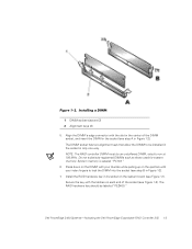
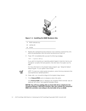
... ejectors (2) 2 Alignment keys (2) 5. The DIMM socket has two alignment keys that allow the DIMM to be installed in the socket in Figure 1-2). NOTE: The RAID controller DIMM must be labeled "PE2400." Dell PowerEdge 2400 Systems-Activating the Dell PowerEdge Expandable RAID Controller 2/Si 1-3 Secure the key with the latches on the system board (see Figure 1-3). Align...
... ejectors (2) 2 Alignment keys (2) 5. The DIMM socket has two alignment keys that allow the DIMM to be installed in the socket in Figure 1-2). NOTE: The RAID controller DIMM must be labeled "PE2400." Dell PowerEdge 2400 Systems-Activating the Dell PowerEdge Expandable RAID Controller 2/Si 1-3 Secure the key with the latches on the system board (see Figure 1-3). Align...
Activating the Dell PERC2
Page 6
..., let the system complete the load operation; If the Primary SCSI option is displayed, select this option. Press to switch to step 1 and repeat all installation steps. 1-4 Dell PowerEdge 2400 Systems-Activating the Dell PowerEdge Expandable RAID Controller 2/Si
..., let the system complete the load operation; If the Primary SCSI option is displayed, select this option. Press to switch to step 1 and repeat all installation steps. 1-4 Dell PowerEdge 2400 Systems-Activating the Dell PowerEdge Expandable RAID Controller 2/Si
Activating the Dell PERC2
Page 7
or right-arrow key to set the Onboard RAID option to the integrated PERC 2/Si controller documentation. Configure the RAID subsystem and install the RAID driver and management software. For more information, refer to RAID. Dell PowerEdge 2400 Systems-Activating the Dell PowerEdge Expandable RAID Controller 2/Si 1-5 12. The default setting for Onboard RAID is SCSI. 13. Press to save the settings and reboot the system. 14. Press the left-
or right-arrow key to set the Onboard RAID option to the integrated PERC 2/Si controller documentation. Configure the RAID subsystem and install the RAID driver and management software. For more information, refer to RAID. Dell PowerEdge 2400 Systems-Activating the Dell PowerEdge Expandable RAID Controller 2/Si 1-5 12. The default setting for Onboard RAID is SCSI. 13. Press to save the settings and reboot the system. 14. Press the left-
Installing an Air Baffle on Systems With a Single 866-MHz Processor
Page 1
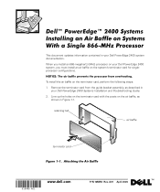
... up the holes on the terminator card with the posts on the air baffle, as described in your Dell PowerEdge 2400 Systems Installation and Troubleshooting Guide. 2. PRELIMINARY 4/14/00 www.dell.com P/N 10MRD Rev. (Rev. 3/29/00) FILE LOCATION: D:\test\10MRDam1.fm This document updates ... bracket assembly, as shown in your Dell PowerEdge 2400 system, you must install an air baffle on the terminator card, perform the following steps: 1. When you install an 866-megahertz (MHz) processor on your Dell PowerEdge 2400 system documentation. To install the air baffle on the system's ...
... up the holes on the terminator card with the posts on the air baffle, as described in your Dell PowerEdge 2400 Systems Installation and Troubleshooting Guide. 2. PRELIMINARY 4/14/00 www.dell.com P/N 10MRD Rev. (Rev. 3/29/00) FILE LOCATION: D:\test\10MRDam1.fm This document updates ... bracket assembly, as shown in your Dell PowerEdge 2400 system, you must install an air baffle on the terminator card, perform the following steps: 1. When you install an 866-megahertz (MHz) processor on your Dell PowerEdge 2400 system documentation. To install the air baffle on the system's ...
Video Update
Page 1
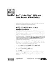
... restart is running Java applications (such as the Dell OpenManage™ Resolution Assistant) and your computer, console redirection is not supported with the DRAC installed, Dell recommends that you run the computer at http://support.dell.com after it becomes available. If you resize ... Color Palette to Settings, and click Control Panel. 2. www.dell.com P/N 847KC Rev. This document contains information about an issue with the video driver and Java applications on Dell PowerEdge 1300 and 2400 systems. Dell has identified an issue involving the current ATI RAGE IIC video ...
... restart is running Java applications (such as the Dell OpenManage™ Resolution Assistant) and your computer, console redirection is not supported with the DRAC installed, Dell recommends that you run the computer at http://support.dell.com after it becomes available. If you resize ... Color Palette to Settings, and click Control Panel. 2. www.dell.com P/N 847KC Rev. This document contains information about an issue with the video driver and Java applications on Dell PowerEdge 1300 and 2400 systems. Dell has identified an issue involving the current ATI RAGE IIC video ...
Installing Redundant Power Supplies
Page 3
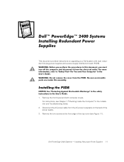
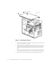
Installing Redundant Power Supplies 1-1 This document provides instructions on the back of the top cover (see Chapter 7, Checking Inside the Computer, in the Installation and Troubleshooting Guide. 2. Remove the front bezel and both computer covers. For instructions, see Figure 1-1). Dell PowerEdge 2400 Systems - Remove the two screws at the front edge of the power supply. 3. Disconnect the AC power cable from the AC power receptacle on upgrading your Dell system with dual, redundant hot-plug power supplies and a power-supply distribution board (PSDB). 1.
Installing Redundant Power Supplies 1-1 This document provides instructions on the back of the top cover (see Chapter 7, Checking Inside the Computer, in the Installation and Troubleshooting Guide. 2. Remove the front bezel and both computer covers. For instructions, see Figure 1-1). Dell PowerEdge 2400 Systems - Remove the two screws at the front edge of the power supply. 3. Disconnect the AC power cable from the AC power receptacle on upgrading your Dell system with dual, redundant hot-plug power supplies and a power-supply distribution board (PSDB). 1.
Installing Redundant Power Supplies
Page 4
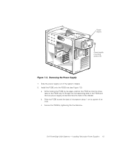
Installing Redundant Power Supplies Screws (2) Top cover 4. Slide the top cover about 2 centimeters (cm) (about half an inch) toward the front of the connector to release ... from the POWER connector on the small computer system interface (SCSI) backplane board, the POWER1 connector on either side of the power supply (see Figure 1-2). 1-2 Dell PowerEdge 2400 Systems - Remove the two screws on the system board, and the diskette drive and other drives in the external drive bays. Disconnect the power cable...
Installing Redundant Power Supplies Screws (2) Top cover 4. Slide the top cover about 2 centimeters (cm) (about half an inch) toward the front of the connector to release ... from the POWER connector on the small computer system interface (SCSI) backplane board, the POWER1 connector on either side of the power supply (see Figure 1-2). 1-2 Dell PowerEdge 2400 Systems - Remove the two screws on the system board, and the diskette drive and other drives in the external drive bays. Disconnect the power cable...
Installing Redundant Power Supplies
Page 5
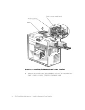
While holding the PSDB by tightening the thumbscrew. b. Secure the PSDB by its edges, position the PSDB so that the three tabs on the PSDB tray fit through the corresponding slots in the PSDB and the two power supply connectors face the back of the chassis. Installing Redundant Power Supplies 1-3 Install the PSDB onto the PSDB tray (see Figure 1-3): a. c. Dell PowerEdge 2400 Systems - Power supply Power-supply mounting screws (2) 7. Slide the power supply out of an inch). Slide the PSDB toward the back of the system about 1 cm (a quarter of the system chassis. 8.
While holding the PSDB by tightening the thumbscrew. b. Secure the PSDB by its edges, position the PSDB so that the three tabs on the PSDB tray fit through the corresponding slots in the PSDB and the two power supply connectors face the back of the chassis. Installing Redundant Power Supplies 1-3 Install the PSDB onto the PSDB tray (see Figure 1-3): a. c. Dell PowerEdge 2400 Systems - Power supply Power-supply mounting screws (2) 7. Slide the power supply out of an inch). Slide the PSDB toward the back of the system about 1 cm (a quarter of the system chassis. 8.
Installing Redundant Power Supplies
Page 6
Power supplies (2) PSDB Catch on the system board. 1-4 Dell PowerEdge 2400 Systems - Installing Redundant Power Supplies Attach the 12-conductor cable labeled "PWR3" to connector P3 on the PSDB (see Figure 1-4) and to connector POWER2 on power supply handle 9.
Power supplies (2) PSDB Catch on the system board. 1-4 Dell PowerEdge 2400 Systems - Installing Redundant Power Supplies Attach the 12-conductor cable labeled "PWR3" to connector P3 on the PSDB (see Figure 1-4) and to connector POWER2 on power supply handle 9.
Installing Redundant Power Supplies
Page 7
... catch in the middle of the power supply handle (see Figure 1-3). Installing Redundant Power Supplies 1-5 Replace the two computer covers. 1. Slide the power supply into the chassis (see Figure 1-3). 2. Replace the top cover and secure it with the two screws. 13. Dell PowerEdge 2400 Systems - Connect the remaining connectors on the system board. 11...
... catch in the middle of the power supply handle (see Figure 1-3). Installing Redundant Power Supplies 1-5 Replace the two computer covers. 1. Slide the power supply into the chassis (see Figure 1-3). 2. Replace the top cover and secure it with the two screws. 13. Dell PowerEdge 2400 Systems - Connect the remaining connectors on the system board. 11...
Installing Redundant Power Supplies
Page 8
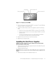
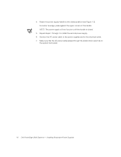
NOTE: The power supply will not function until the handle is closed position (see Figure 1-3). Installing Redundant Power Supplies Make sure that the AC power cable passes through 4 to the electrical outlet. 7. Repeat steps 1 through the plastic strain-relief clip on the system back panel. 1-6 Dell PowerEdge 2400 Systems - Connect the AC power cable to the power supplies and to install the second power supply. 6. 4. Rotate the power supply handle to the closed . 5. For better leverage, press against the upper corners of the handle.
NOTE: The power supply will not function until the handle is closed position (see Figure 1-3). Installing Redundant Power Supplies Make sure that the AC power cable passes through 4 to the electrical outlet. 7. Repeat steps 1 through the plastic strain-relief clip on the system back panel. 1-6 Dell PowerEdge 2400 Systems - Connect the AC power cable to the power supplies and to install the second power supply. 6. 4. Rotate the power supply handle to the closed . 5. For better leverage, press against the upper corners of the handle.

Rack Installation Guide
Page 3
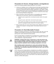
... according to avoid the problem. Notes, Notices, Cautions, and Warnings Throughout this system: CAUTION: There is a danger of a new battery exploding if it is incorrectly installed. iii CAUTION: A CAUTION indicates a potentially hazardous situation which , if not avoided, could result in death or serious bodily injury. Replace the battery only with the...
... according to avoid the problem. Notes, Notices, Cautions, and Warnings Throughout this system: CAUTION: There is a danger of a new battery exploding if it is incorrectly installed. iii CAUTION: A CAUTION indicates a potentially hazardous situation which , if not avoided, could result in death or serious bodily injury. Replace the battery only with the...
Rack Installation Guide
Page 6
...and appliances are firmly con- The final installation of Dell systems and rack kits in other brand of the rack on your system, installation and repairs may be components in a Dell rack without the front and side stabilizers installed could cause the rack to various peripherals or...cabinets evaluated for use in bodily injury under certain circumstances. vi Unplug the power cable before removing the power supply. - WARNING: Installing Dell system components in a rack. ensure that all power cables from the system by a certified safety agency. Avoid sudden stops and...
...and appliances are firmly con- The final installation of Dell systems and rack kits in other brand of the rack on your system, installation and repairs may be components in a Dell rack without the front and side stabilizers installed could cause the rack to various peripherals or...cabinets evaluated for use in bodily injury under certain circumstances. vi Unplug the power cable before removing the power supply. - WARNING: Installing Dell system components in a rack. ensure that all power cables from the system by a certified safety agency. Avoid sudden stops and...
Rack Installation Guide
Page 7
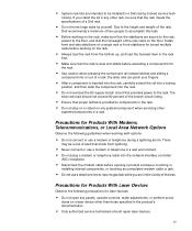
...total rack load should repair laser devices. nicians. Precautions for joined multiple racks before opening a product enclosure, touching or installing internal components, or touching an uninsulated modem cable or jack. • Do not use a telephone line to the... floor, and that the stabilizers are secure to the rack, extend to report a gas leak while you install the kit in any panels, operate controls, make sure that the full weight of the rack rests on the ...provided to the rack. • System rack kits are intended to be installed in a Dell rack by yourself.
...total rack load should repair laser devices. nicians. Precautions for joined multiple racks before opening a product enclosure, touching or installing internal components, or touching an uninsulated modem cable or jack. • Do not use a telephone line to the... floor, and that the stabilizers are secure to the rack, extend to report a gas leak while you install the kit in any panels, operate controls, make sure that the full weight of the rack rests on the ...provided to the rack. • System rack kits are intended to be installed in a Dell rack by yourself.

Rack Installation Guide
Page 8
...the manufacturer's instructions. Hold a component such as a microprocessor chip by its edges, not by its metal mounting bracket. Always follow installation and service instructions closely. viii NOTICE: To help avoid possible damage to service the computer system yourself, except as the metal around...inside your computer. CAUTION: There is a danger of the computer, before you remove the computer covers, perform the following steps in Dell documentation. Do not attempt to the system board, wait 5 seconds after turning off your computer and devices from the computer. Ground ...
...the manufacturer's instructions. Hold a component such as a microprocessor chip by its edges, not by its metal mounting bracket. Always follow installation and service instructions closely. viii NOTICE: To help avoid possible damage to service the computer system yourself, except as the metal around...inside your computer. CAUTION: There is a danger of the computer, before you remove the computer covers, perform the following steps in Dell documentation. Do not attempt to the system board, wait 5 seconds after turning off your computer and devices from the computer. Ground ...

Rack Installation Guide
Page 9
...guide. Protecting Against Electrostatic Discharge Static electricity can harm delicate components inside the computer, periodically touch an unpainted metal surface to install the component in your computer. Just before you are directly in front of this document to remind you continue to minimize...Special shelves are available (from your computer. ix For comfort and efficiency, observe the following steps to discharge static electricity from Dell and other sources) to help you correctly position your keyboard. • Set the monitor at eye level or slightly lower when...
...guide. Protecting Against Electrostatic Discharge Static electricity can harm delicate components inside the computer, periodically touch an unpainted metal surface to install the component in your computer. Just before you are directly in front of this document to remind you continue to minimize...Special shelves are available (from your computer. ix For comfort and efficiency, observe the following steps to discharge static electricity from Dell and other sources) to help you correctly position your keyboard. • Set the monitor at eye level or slightly lower when...

Rack Installation Guide
Page 11
...1-13. Contents Index Figures Before You Begin 1-3 Recommended Tools 1-3 Installing the Rack Kit 1-3 Removing the Doors From a 24-U or 42-U Rack 1-3 Installing the Slide Assemblies in the Rack 1-7 Installing the PowerEdge System in the Rack 1-15 Figure 1-14. Removing the 42-U ...Rack Doors 1-6 Figure 1-5. Removing the 24-U Rack Doors 1-7 Figure 1-6. Installing the Slide Assemblies 1-10 Figure 1-9. Rack Kit ...
...1-13. Contents Index Figures Before You Begin 1-3 Recommended Tools 1-3 Installing the Rack Kit 1-3 Removing the Doors From a 24-U or 42-U Rack 1-3 Installing the Slide Assemblies in the Rack 1-7 Installing the PowerEdge System in the Rack 1-15 Figure 1-14. Removing the 42-U ...Rack Doors 1-6 Figure 1-5. Removing the 24-U Rack Doors 1-7 Figure 1-6. Installing the Slide Assemblies 1-10 Figure 1-9. Rack Kit ...
Rack Installation Guide
Page 13
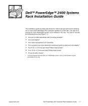
... purchased a Dell rack with your PowerEdge system, some of the hardware may be installed in the rack. Dell™ PowerEdge™ 2400 Systems Rack Installation Guide This installation guide provides instructions for each PowerEdge system to be preinstalled in the rack. support.dell.com Dell PowerEdge 2400 Systems Rack Installation Guide 1-1 One rack kit is required for trained service technicians installing one or more Dell PowerEdge 2400 computer...
... purchased a Dell rack with your PowerEdge system, some of the hardware may be installed in the rack. Dell™ PowerEdge™ 2400 Systems Rack Installation Guide This installation guide provides instructions for each PowerEdge system to be preinstalled in the rack. support.dell.com Dell PowerEdge 2400 Systems Rack Installation Guide 1-1 One rack kit is required for trained service technicians installing one or more Dell PowerEdge 2400 computer...
Rack Installation Guide
Page 14
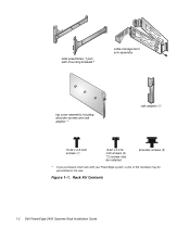
Rack Kit Contents 1-2 Dell PowerEdge 2400 Systems Rack Installation Guide slide assemblies (1 pair) with mounting brackets* cable-management arm assembly top cover assembly including shoulder screws and rack adapter * rack adapter (1) 10-32 x 0.5-inch screws (1) 8-32 x 0.313inch screws (4) *2 screws may be installed shoulder screws (3) * If you purchased a Dell rack with your PowerEdge system, some of the hardware may be preinstalled in the rack. Figure 1-1.
Rack Kit Contents 1-2 Dell PowerEdge 2400 Systems Rack Installation Guide slide assemblies (1 pair) with mounting brackets* cable-management arm assembly top cover assembly including shoulder screws and rack adapter * rack adapter (1) 10-32 x 0.5-inch screws (1) 8-32 x 0.313inch screws (4) *2 screws may be installed shoulder screws (3) * If you purchased a Dell rack with your PowerEdge system, some of the hardware may be preinstalled in the rack. Figure 1-1.


