

Installing a SATA Optical Drive
Page 3
...Systems 1 Turn off the system and attached peripherals, and disconnect the system from the center fan bracket. Before you begin this procedure, review the safety instructions that came with a drive tray...Optical Drive - Installing a SATA Optical Drive These instructions apply to Dell™ PowerEdge™ systems to remove the system cover and access any of the optical drive. 6 PowerEdge 2900 and 1900 systems only: Perform the following steps. See ... being added, or in your Hardware Owner's Manual. 4 PowerEdge 1950 systems only: Disconnect and remove the SAS controller daughter card.
...Systems 1 Turn off the system and attached peripherals, and disconnect the system from the center fan bracket. Before you begin this procedure, review the safety instructions that came with a drive tray...Optical Drive - Installing a SATA Optical Drive These instructions apply to Dell™ PowerEdge™ systems to remove the system cover and access any of the optical drive. 6 PowerEdge 2900 and 1900 systems only: Perform the following steps. See ... being added, or in your Hardware Owner's Manual. 4 PowerEdge 1950 systems only: Disconnect and remove the SAS controller daughter card.

Installing a SATA Optical Drive
Page 6
...cable) to the back of the chipset shroud. c Connect the cable to the SATA_A connector on the system board. See Figure 1-3. Figure 1-2. PowerEdge 1950 1 Insert the optical drive tray into the system until it is fully inserted and locked into the cable path on the system board. 6 ... cable through the power cable cutout in the fan bracket and follow the power cable routing to the power supply connector. b Bend the cable toward the chipset shroud and insert the cable into position. 2 Connect the SATA cable (the end with a cable provided in a PowerEdge 1950 Drive Tray 2 3 1 4 5 1 ...
...cable) to the back of the chipset shroud. c Connect the cable to the SATA_A connector on the system board. See Figure 1-3. Figure 1-2. PowerEdge 1950 1 Insert the optical drive tray into the system until it is fully inserted and locked into the cable path on the system board. 6 ... cable through the power cable cutout in the fan bracket and follow the power cable routing to the power supply connector. b Bend the cable toward the chipset shroud and insert the cable into position. 2 Connect the SATA cable (the end with a cable provided in a PowerEdge 1950 Drive Tray 2 3 1 4 5 1 ...

Installing a SATA Optical Drive
Page 7
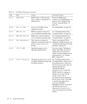
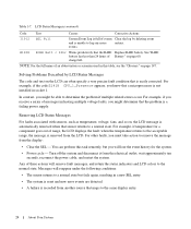
See "SAS Controller Daughter Card" in your Hardware Owner's Manual. 6 Close the system. Installing a SATA Optical Drive 7 SATA Cable Routing in the PowerEdge 1950 2 1 3 4 6 5 1 SATA data cable 3 chipset shroud 5 SATA power cable 2 SATA_A connector on the system and attached peripherals. Installing the SATA Optical Drive - See "Closing the ... branching power cable) to the back of the optical drive. 3 Connect the branching power cable to power and turn on system board 4 system fans 6 optical drive 5 Reinstall the SAS controller daughter card and reconnect the SAS cable.
See "SAS Controller Daughter Card" in your Hardware Owner's Manual. 6 Close the system. Installing a SATA Optical Drive 7 SATA Cable Routing in the PowerEdge 1950 2 1 3 4 6 5 1 SATA data cable 3 chipset shroud 5 SATA power cable 2 SATA_A connector on the system and attached peripherals. Installing the SATA Optical Drive - See "Closing the ... branching power cable) to the back of the optical drive. 3 Connect the branching power cable to power and turn on system board 4 system fans 6 optical drive 5 Reinstall the SAS controller daughter card and reconnect the SAS cable.

Installing a SATA Optical Drive
Page 9
...Connect the SATA cable to the back of the fan bracket and connect the cable to the CD/TBU connector on the system backplane. See Figure 1-5. - See Figure 1-5. - Installing a SATA Optical Drive 9 9 Replace the cooling shroud. For a PowerEdge 1900 system, connect to the power supply as... follows: - For a PowerEdge 2900, use the SATA_D connector. For a PowerEdge 2900 system, connect to the SATA connector on the system and attached peripherals. See "Replacing the Center Fan Bracket" in your Hardware Owner's Manual. 6 Replace the fans in the center fan bracket. 7 Route the SATA ...
...Connect the SATA cable to the back of the fan bracket and connect the cable to the CD/TBU connector on the system backplane. See Figure 1-5. - See Figure 1-5. - Installing a SATA Optical Drive 9 9 Replace the cooling shroud. For a PowerEdge 1900 system, connect to the power supply as... follows: - For a PowerEdge 2900, use the SATA_D connector. For a PowerEdge 2900 system, connect to the SATA connector on the system and attached peripherals. See "Replacing the Center Fan Bracket" in your Hardware Owner's Manual. 6 Replace the fans in the center fan bracket. 7 Route the SATA ...
Information Update
Page 16
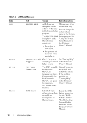
..., the persists, see thermal issues. ROMB Batt RAID battery is for critical in the Hardware to Battery" and see BMC increases "Getting Help" the CPU fan speed in the Hardware failure events.
..., the persists, see thermal issues. ROMB Batt RAID battery is for critical in the Hardware to Battery" and see BMC increases "Getting Help" the CPU fan speed in the Hardware failure events.
Hardware Owner's Manual (PDF)
Page 4
... 45 Opening and Closing the System 46 Opening the System 46 Closing the System 47 Cooling Fan Modules 48 Removing a Cooling Fan Module 48 Replacing a Cooling Fan Module 49 Removing the Plastic Fan Guide 50 Replacing the Plastic Fan Guide 50 Cooling Shrouds 50 System Board Cooling Shroud 50 Memory Cooling Shroud 52 Power Supplies...
... 45 Opening and Closing the System 46 Opening the System 46 Closing the System 47 Cooling Fan Modules 48 Removing a Cooling Fan Module 48 Replacing a Cooling Fan Module 49 Removing the Plastic Fan Guide 50 Replacing the Plastic Fan Guide 50 Cooling Shrouds 50 System Board Cooling Shroud 50 Memory Cooling Shroud 52 Power Supplies...
Hardware Owner's Manual (PDF)
Page 7
Troubleshooting the System Battery 100 Troubleshooting Power Supplies 100 Troubleshooting System Cooling Problems 101 Troubleshooting a Fan 101 Troubleshooting System Memory 102 Troubleshooting an Optical Drive 103 Troubleshooting a Hard Drive 104 Troubleshooting a SAS or SAS RAID Controller Daughter Card 105 Troubleshooting Expansion ...
Troubleshooting the System Battery 100 Troubleshooting Power Supplies 100 Troubleshooting System Cooling Problems 101 Troubleshooting a Fan 101 Troubleshooting System Memory 102 Troubleshooting an Optical Drive 103 Troubleshooting a Hard Drive 104 Troubleshooting a SAS or SAS RAID Controller Daughter Card 105 Troubleshooting Expansion ...
Hardware Owner's Manual (PDF)
Page 12
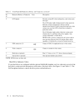
... figure). Table 1-2. NOTE: If the system is connected to the system. 7 Hard drives (optional) 8 Optical drive (optional) NOTE: DVD devices are configured with power supplies, fans, system temperature, or hard drives. One optional slimline optical drive Hard-Drive Indicator Codes If your hard drives are data only. See Figure 1-2 and Table 1-3.
... figure). Table 1-2. NOTE: If the system is connected to the system. 7 Hard drives (optional) 8 Optical drive (optional) NOTE: DVD devices are configured with power supplies, fans, system temperature, or hard drives. One optional slimline optical drive Hard-Drive Indicator Codes If your hard drives are data only. See Figure 1-2 and Table 1-3.
Hardware Owner's Manual (PDF)
Page 18
... See "Troubleshooting System out of acceptable operating range. RPM of fan x in the # module is out of over- Problems" on page 108. See "Troubleshooting the Microprocessors" on page 101. See the Dell OpenManage Baseboard Management Controller User's Guide for the most current system information. Reseat the RAID battery connector. Cooling Problems" on...
... See "Troubleshooting System out of acceptable operating range. RPM of fan x in the # module is out of over- Problems" on page 108. See "Troubleshooting the Microprocessors" on page 101. See the Dell OpenManage Baseboard Management Controller User's Guide for the most current system information. Reseat the RAID battery connector. Cooling Problems" on...
Hardware Owner's Manual (PDF)
Page 24
... system. In contrast, you might determine that the RAID Replace RAID battery. Removing LCD Status Messages For faults associated with sensors, such as temperature, voltage, fans, and so on page 60. when the temperature returns to the acceptable range, the message is unable to determine the problem if multiple related errors...
... system. In contrast, you might determine that the RAID Replace RAID battery. Removing LCD Status Messages For faults associated with sensors, such as temperature, voltage, fans, and so on page 60. when the temperature returns to the acceptable range, the message is unable to determine the problem if multiple related errors...
Hardware Owner's Manual (PDF)
Page 30
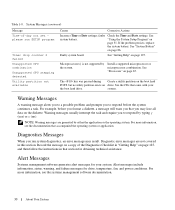
... more information, see the documentation that you that accompanied the operating system or application. Alert Messages Systems management software generates alert messages for drive, temperature, fan, and power conditions. system. For more information, see the systems management software documentation. 30 About Your System See "Getting Help" on page 67. "Using the...
... more information, see the documentation that you that accompanied the operating system or application. Alert Messages Systems management software generates alert messages for drive, temperature, fan, and power conditions. system. For more information, see the systems management software documentation. 30 About Your System See "Getting Help" on page 67. "Using the...
Hardware Owner's Manual (PDF)
Page 43
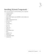
Installing System Components This section describes how to install the following system components: • Cooling fan modules • Cooling shrouds • Power supplies • SAS controller daughter card or SAS RAID controller daughter card • RAID battery • RAID controller expansion ...
Installing System Components This section describes how to install the following system components: • Cooling fan modules • Cooling shrouds • Power supplies • SAS controller daughter card or SAS RAID controller daughter card • RAID battery • RAID controller expansion ...
Hardware Owner's Manual (PDF)
Page 45
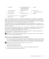
...-length PCI-X cards or two half-length PCIe expansion cards. 1 control panel 2 SAS controller daughter card 3 sideplane or SAS RAID controller daughter card (optional) 4 cooling fan modules (4) 5 power supply bays (2) 6 left end of the bezel away from the system to release the right end of the bezel. 4 Rotate the left riser...
...-length PCI-X cards or two half-length PCIe expansion cards. 1 control panel 2 SAS controller daughter card 3 sideplane or SAS RAID controller daughter card (optional) 4 cooling fan modules (4) 5 power supply bays (2) 6 left end of the bezel away from the system to release the right end of the bezel. 4 Rotate the left riser...

Hardware Owner's Manual (PDF)
Page 48
...48 Installing System Components Damage due to the system board. NOTE: The procedure for a total of eight fans that are connected directly to servicing that is not authorized by Dell is the same. 1 Turn off the system and attached peripherals, and disconnect the system from the ...the chassis. however, Dell recommends that came with the product. NOTE: You can remove the fan modules without removing the memory cooling shroud; Cooling Fan Modules This system contains four cooling fan modules, each comprised of two dual-rotor fans, for removing each individual fan module is not covered...
...48 Installing System Components Damage due to the system board. NOTE: The procedure for a total of eight fans that are connected directly to servicing that is not authorized by Dell is the same. 1 Turn off the system and attached peripherals, and disconnect the system from the ...the chassis. however, Dell recommends that came with the product. NOTE: You can remove the fan modules without removing the memory cooling shroud; Cooling Fan Modules This system contains four cooling fan modules, each comprised of two dual-rotor fans, for removing each individual fan module is not covered...

Hardware Owner's Manual (PDF)
Page 49
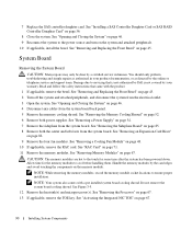
... the system. Installing System Components 49 Then lower the fan handle until it snaps into its retention base until the fan is fully seated. Removing and Installing a Cooling Fan 2 1 3 4 5 1 cooling fan modules (4) 2 fan module handles 3 module wire harness 4 cooling fan module connector 5 system board cooling shroud Replacing a Cooling Fan Module NOTE: The procedure for installing each individual...
... the system. Installing System Components 49 Then lower the fan handle until it snaps into its retention base until the fan is fully seated. Removing and Installing a Cooling Fan 2 1 3 4 5 1 cooling fan modules (4) 2 fan module handles 3 module wire harness 4 cooling fan module connector 5 system board cooling shroud Replacing a Cooling Fan Module NOTE: The procedure for installing each individual...
Hardware Owner's Manual (PDF)
Page 50
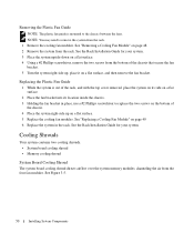
.... See the Rack Installation Guide for your system. 3 Place the system upside-down on a flat surface, and then remove the fan bracket. Replacing the Plastic Fan Guide 1 While the system is mounted to remove the system from the bottom of the chassis. 4 Place the system right-side up , place ...it on a flat surface. 4 Using a #2 Phillips screwdriver, remove the two screws from the rack. 1 Remove the cooling fan modules. Removing the Plastic Fan Guide NOTE: The plastic fan guide is out of the rack, and with the top cover removed, place the system on its side on a flat surface...
.... See the Rack Installation Guide for your system. 3 Place the system upside-down on a flat surface, and then remove the fan bracket. Replacing the Plastic Fan Guide 1 While the system is mounted to remove the system from the bottom of the chassis. 4 Place the system right-side up , place ...it on a flat surface. 4 Using a #2 Phillips screwdriver, remove the two screws from the rack. 1 Remove the cooling fan modules. Removing the Plastic Fan Guide NOTE: The plastic fan guide is out of the rack, and with the top cover removed, place the system on its side on a flat surface...
Hardware Owner's Manual (PDF)
Page 90
...Read and follow the safety instructions that is not authorized by Dell is not covered by the card edges and avoid touching the...memory modules are hot to ensure proper installation. See "Removing the Processor" on page 82. 9 Remove the four fan modules. 7 Replace the SAS controller daughter card. See "Installing a SAS Controller Daughter Card or SAS RAID Controller ...or as directed by a certified service technician. Do not remove the system board cooling shroud. See "Removing a Cooling Fan Module" on page 56. 8 Close the system. See "RAC Card" on page 45. NOTE: Your system also ...
...Read and follow the safety instructions that is not authorized by Dell is not covered by the card edges and avoid touching the...memory modules are hot to ensure proper installation. See "Removing the Processor" on page 82. 9 Remove the four fan modules. 7 Replace the SAS controller daughter card. See "Installing a SAS Controller Daughter Card or SAS RAID Controller ...or as directed by a certified service technician. Do not remove the system board cooling shroud. See "Removing a Cooling Fan Module" on page 56. 8 Close the system. See "RAC Card" on page 45. NOTE: Your system also ...
Hardware Owner's Manual (PDF)
Page 92
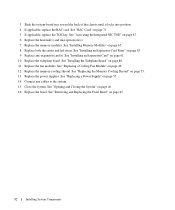
... microprocessor(s). 7 Replace the memory modules. See "Installing an Expansion-Card Riser" on page 49. 12 Replace the memory cooling shroud. See "Replacing a Cooling Fan Module" on page 83. 9 Replace any cables to the system. 15 Close the system. See "Removing and Replacing the Front Bezel" on page 61. ... "Installing Memory Modules" on page 53. 13 Replace the power supplies. See "Installing the Sideplane Board" on page 86. 11 Replace the fan modules. 3 Slide the system-board tray toward the back of the chassis until it locks into position. 4 If applicable, replace the RAC card.
... microprocessor(s). 7 Replace the memory modules. See "Installing an Expansion-Card Riser" on page 49. 12 Replace the memory cooling shroud. See "Replacing a Cooling Fan Module" on page 83. 9 Replace any cables to the system. 15 Close the system. See "Removing and Replacing the Front Bezel" on page 61. ... "Installing Memory Modules" on page 53. 13 Replace the power supplies. See "Installing the Sideplane Board" on page 86. 11 Replace the fan modules. 3 Slide the system-board tray toward the back of the chassis until it locks into position. 4 If applicable, replace the RAC card.
Hardware Owner's Manual (PDF)
Page 99
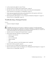
...components are properly installed: • Expansion cards and risers • Power supplies • Processor and heatsink • Memory modules • Fans • Drive-carrier connections to servicing that came with the product. 1 Open the system. See "Opening and Closing the System" on page... a Damaged System Problem • System was dropped or damaged. Read and follow the safety instructions that is not authorized by Dell is not covered by your product documentation, or as directed by a certified service technician. See "Running the System Diagnostics" on...
...components are properly installed: • Expansion cards and risers • Power supplies • Processor and heatsink • Memory modules • Fans • Drive-carrier connections to servicing that came with the product. 1 Open the system. See "Opening and Closing the System" on page... a Damaged System Problem • System was dropped or damaged. Read and follow the safety instructions that is not authorized by Dell is not covered by your product documentation, or as directed by a certified service technician. See "Running the System Diagnostics" on...
Hardware Owner's Manual (PDF)
Page 101
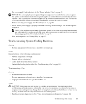
...or telephone service and support team. Remove the faulty power supply. See "Troubleshooting a Fan" on page 111. Read and follow the safety instructions that is not authorized by Dell is not covered by removing and reinstalling it is lit. Operating the system for the..." on page 15. Action Ensure that is obstructed. • Cables inside the system obstruct airflow. • An individual cooling fan has failed. Troubleshooting a Fan Problem • System-status indicator is properly installed by your product documentation, or as directed by a certified service technician. The...
...or telephone service and support team. Remove the faulty power supply. See "Troubleshooting a Fan" on page 111. Read and follow the safety instructions that is not authorized by Dell is not covered by removing and reinstalling it is lit. Operating the system for the..." on page 15. Action Ensure that is obstructed. • Cables inside the system obstruct airflow. • An individual cooling fan has failed. Troubleshooting a Fan Problem • System-status indicator is properly installed by your product documentation, or as directed by a certified service technician. The...


