
Information Update
Page 3
... Performance Features 5 New High-Efficiency Power Supply and Power Monitoring Features 5 New I/O and Storage Features 6 New Security Features 6 Optional Internal USB Memory Key 6 Installing the Optional Internal USB Memory Key . . 8 Support for 8-GB Memory Modules - Safeguarding Encrypted Data 10 System Message Update 10 LCD Status Messages Update 15 Contents 3 Contents Non-Optimal Memory Configurations 5 PowerEdge 1950 III -
... Performance Features 5 New High-Efficiency Power Supply and Power Monitoring Features 5 New I/O and Storage Features 6 New Security Features 6 Optional Internal USB Memory Key 6 Installing the Optional Internal USB Memory Key . . 8 Support for 8-GB Memory Modules - Safeguarding Encrypted Data 10 System Message Update 10 LCD Status Messages Update 15 Contents 3 Contents Non-Optimal Memory Configurations 5 PowerEdge 1950 III -
Information Update
Page 5
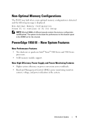
... • Two dual-core or quad-core Intel® Xeon® 5400 Series and 5300 Series processors. • 8-GB memory module support. PowerEdge 1950 III - Non-Optimal Memory Configurations The POST may halt when a non-optimal memory configuration is detected and the following message is displayed: Non-Optimal Memory Configuration Press F1 to the slowest speed in the system.
... • Two dual-core or quad-core Intel® Xeon® 5400 Series and 5300 Series processors. • 8-GB memory module support. PowerEdge 1950 III - Non-Optimal Memory Configurations The POST may halt when a non-optimal memory configuration is detected and the following message is displayed: Non-Optimal Memory Configuration Press F1 to the slowest speed in the system.
Information Update
Page 7
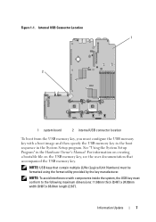
See "Using the System Setup Program" in the System Setup program. For information on creating a bootable file on the USB memory key, see the user documentation that contain multiple LUNs (Logical Unit Numbers) must conform to the following maximum dimensions: 11.68mm thick ... Information Update 7 Internal USB Connector Location 1 2 1 system board 2 internal USB connector location To boot from the USB memory key, you must configure the USB memory key with components inside the system, the USB key must be formatted using the format utility provided by the key manufacturer. ...
See "Using the System Setup Program" in the System Setup program. For information on creating a bootable file on the USB memory key, see the user documentation that contain multiple LUNs (Logical Unit Numbers) must conform to the following maximum dimensions: 11.68mm thick ... Information Update 7 Internal USB Connector Location 1 2 1 system board 2 internal USB connector location To boot from the USB memory key, you must configure the USB memory key with components inside the system, the USB key must be formatted using the format utility provided by the key manufacturer. ...
Information Update
Page 9
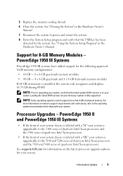
... system documentation that your system. See support.dell.com for information on your system is on the latest processor upgrade options for 8-GB Memory Modules - See "Closing the System" in the Hardware Owner's Manual. PowerEdge 1950 III Systems PowerEdge 1950 III systems have added support for the following approved 8-GB memory configurations: • 64 GB - 8 x 8-GB quad-rank...
... system documentation that your system. See support.dell.com for information on your system is on the latest processor upgrade options for 8-GB Memory Modules - See "Closing the System" in the Hardware Owner's Manual. PowerEdge 1950 III Systems PowerEdge 1950 III systems have added support for the following approved 8-GB memory configurations: • 64 GB - 8 x 8-GB quad-rank...
Information Update
Page 11
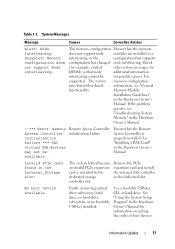
...PCIe expansion expansion card and install card is properly installed. The system memory configuration runs but with reduced information, see "Troubleshooting System Memory" in the Hardware Owner's Manual. !!*** Error: Remote Access Controller initialization... causes. If the problem persists, see "General functionality. Node Interleaving disabled! Memory configuration does not support Node Interleaving. The memory configuration Ensure that supports configuration has changed node interleaving. Ensure that node additional information interleaving cannot be available......
...PCIe expansion expansion card and install card is properly installed. The system memory configuration runs but with reduced information, see "Troubleshooting System Memory" in the Hardware Owner's Manual. !!*** Error: Remote Access Controller initialization... causes. If the problem persists, see "General functionality. Node Interleaving disabled! Memory configuration does not support Node Interleaving. The memory configuration Ensure that supports configuration has changed node interleaving. Ensure that node additional information interleaving cannot be available......
Information Update
Page 15
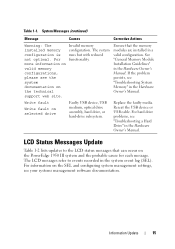
... Causes Corrective Actions Warning: The installed memory configuration is not optimal. Invalid memory configuration. LCD Status Messages Update Table 1-2 lists updates to events recorded in the Hardware Owner's Manual. Information Update 15 For more information on the PowerEdge 1950 III system and the probable cause for each message. See "General Memory Module Installation Guidelines" in the system...
... Causes Corrective Actions Warning: The installed memory configuration is not optimal. Invalid memory configuration. LCD Status Messages Update Table 1-2 lists updates to events recorded in the Hardware Owner's Manual. Information Update 15 For more information on the PowerEdge 1950 III system and the probable cause for each message. See "General Memory Module Installation Guidelines" in the system...
Information Update
Page 21
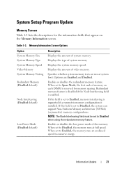
... Interleaving (Disabled default) Low Power Mode (Disabled default) Description Displays the amount of the memory. Displays the amount of system memory. When set to Enabled, the memory runs at a reduced speed to Disabled, the system can support Non-Uniform Memory architecture (NUMA) (asymmetric) memory configurations. If this field is set to Disabled when using the redundant...
... Interleaving (Disabled default) Low Power Mode (Disabled default) Description Displays the amount of the memory. Displays the amount of system memory. When set to Enabled, the memory runs at a reduced speed to Disabled, the system can support Non-Uniform Memory architecture (NUMA) (asymmetric) memory configurations. If this field is set to Disabled when using the redundant...
Information Update
Page 31
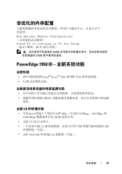
POST Non-Optimal Memory Configuration Press F1 to continue or F2 for Setup (按 F1 F2 DIMM DIMM PowerEdge 1950 III 全新性能 Intel® Xeon® 5400 系列和 5300 8 GB BMC 使用。 全新 I/O • 可选 Intel NIC 10 Mbps、100 Mbps 和 1000 Mbps iSCSI • 支持 10 Gb USB 2.0 USB USB SAS 6i/R 和 PERC 6/i 信息更新 31
POST Non-Optimal Memory Configuration Press F1 to continue or F2 for Setup (按 F1 F2 DIMM DIMM PowerEdge 1950 III 全新性能 Intel® Xeon® 5400 系列和 5300 8 GB BMC 使用。 全新 I/O • 可选 Intel NIC 10 Mbps、100 Mbps 和 1000 Mbps iSCSI • 支持 10 Gb USB 2.0 USB USB SAS 6i/R 和 PERC 6/i 信息更新 31
Information Update
Page 40
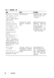
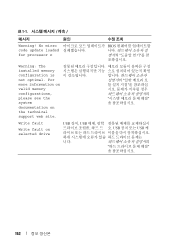
表 1-1 信息 原因 纠正措施 Warning! For more information on valid memory configurations, please see the system documentation on the technical support web site Write fault USB 设备、USB Write fault on selected drive USB 设备或 USB 40 信息更新 No micro code update loaded for processor n n 请更新 BIOS Warning: The installed memory configuration is not optimal.
表 1-1 信息 原因 纠正措施 Warning! For more information on valid memory configurations, please see the system documentation on the technical support web site Write fault USB 设备、USB Write fault on selected drive USB 设备或 USB 40 信息更新 No micro code update loaded for processor n n 请更新 BIOS Warning: The installed memory configuration is not optimal.
Information Update
Page 115
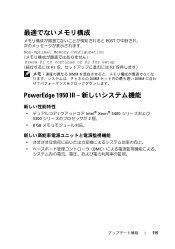
POST Non-Optimal Memory Configuration Press F1 to continue or F2 for Setup F1 F2 DIMM DIMM DIMM PowerEdge 1950 III Intel® Xeon® 5400 5300 2 個。 • 8 GB BMC 115
POST Non-Optimal Memory Configuration Press F1 to continue or F2 for Setup F1 F2 DIMM DIMM DIMM PowerEdge 1950 III Intel® Xeon® 5400 5300 2 個。 • 8 GB BMC 115
Information Update
Page 121
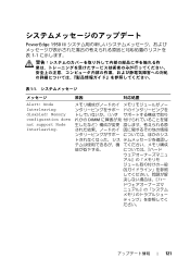
Memory configuration does not support Node Interleaving. れかの DIMM ださい。 121 Node Interleaving disabled! PowerEdge 1950 III 1-1 表 1-1 原因 対応処置 Alert!
Memory configuration does not support Node Interleaving. れかの DIMM ださい。 121 Node Interleaving disabled! PowerEdge 1950 III 1-1 表 1-1 原因 対応処置 Alert!
Information Update
Page 126
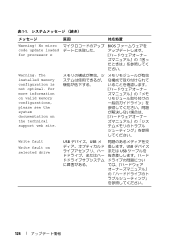
Write fault Write fault on the technical support web site. 表 1-1 原因 対応処置 Warning! For more information on valid memory configurations, please see the system documentation on selected drive USB USB USB USB 126 No micro code update loaded for processor n BIOS ださい。 Warning: The installed memory configuration is not optimal.
Write fault Write fault on the technical support web site. 表 1-1 原因 対応処置 Warning! For more information on valid memory configurations, please see the system documentation on selected drive USB USB USB USB 126 No micro code update loaded for processor n BIOS ださい。 Warning: The installed memory configuration is not optimal.

Information Update
Page 143
POST Non-Optimal Memory Configuration Press F1 to continue or F2 for Setup F1 F2 DIMM DIMM PowerEdge 1950 III Intel® Xeon® 5400 5300 • 8GB BMC (Baseboard Management Control 143
POST Non-Optimal Memory Configuration Press F1 to continue or F2 for Setup F1 F2 DIMM DIMM PowerEdge 1950 III Intel® Xeon® 5400 5300 • 8GB BMC (Baseboard Management Control 143
Information Update
Page 152
No micro code update loaded for processor n BIOS Warning: The installed memory configuration is not optimal. For more information on valid memory configurations, please see the system documentation on selected drive USB 장치, USB USB USB 케 니다. 152 표 1-1 메시지 원인 Warning! Write fault Write fault on the technical support web site.
No micro code update loaded for processor n BIOS Warning: The installed memory configuration is not optimal. For more information on valid memory configurations, please see the system documentation on selected drive USB 장치, USB USB USB 케 니다. 152 표 1-1 메시지 원인 Warning! Write fault Write fault on the technical support web site.

Hardware Owner's Manual (PDF)
Page 5
... 61 Installing an Expansion Card 61 Removing an Expansion Card 62 Configuring the Boot Device 63 Configuring the Boot Drive 63 System Memory 63 General Memory Module Installation Guidelines 64 Non-Optimal Memory Configurations 64 Memory Sparing Support 64 Memory Mirroring Support 65 Installing Memory Modules 65 Removing Memory Modules 67 Activating the Integrated NIC TOE 67 Processors 67 Removing...
... 61 Installing an Expansion Card 61 Removing an Expansion Card 62 Configuring the Boot Device 63 Configuring the Boot Drive 63 System Memory 63 General Memory Module Installation Guidelines 64 Non-Optimal Memory Configurations 64 Memory Sparing Support 64 Memory Mirroring Support 65 Installing Memory Modules 65 Removing Memory Modules 67 Activating the Integrated NIC TOE 67 Processors 67 Removing...

Hardware Owner's Manual (PDF)
Page 21
... is installed in the system. persists, replace the cable. Reseat the cable. No Memory No memory is missing or Reseat the cable. Install memory. See "Installing Memory Modules" on page 102. Error detected during memory configuration. Unusable Memory Memory is configured, but is missing or bad. Memory" on page 65. CMOS RAM not See "Getting Help" on page 125. functioning...
... is installed in the system. persists, replace the cable. Reseat the cable. No Memory No memory is missing or Reseat the cable. Install memory. See "Installing Memory Modules" on page 102. Error detected during memory configuration. Unusable Memory Memory is configured, but is missing or bad. Memory" on page 65. CMOS RAM not See "Getting Help" on page 125. functioning...
Hardware Owner's Manual (PDF)
Page 22
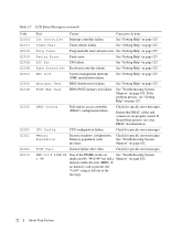
...System management interrupt (SMI) initialization failure. POST Mem Test BIOS POST memory test failure. If the problem persists, see your DRAC documentation. Memory Population Incorrect memory configuration. Memory population order incorrect. memory multi-bit error (MBE). See "Getting Help" on page 125....Programmable interval timer error. POST Fail General failure after video. See "Getting Help" on page 125. DRAC Config Dell remote access controller (DRAC) configuration failure. Check for specific error messages. MBE Crd # DIMM ## & ## One of the message. 22 About...
...System management interrupt (SMI) initialization failure. POST Mem Test BIOS POST memory test failure. If the problem persists, see your DRAC documentation. Memory Population Incorrect memory configuration. Memory population order incorrect. memory multi-bit error (MBE). See "Getting Help" on page 125....Programmable interval timer error. POST Fail General failure after video. See "Getting Help" on page 125. DRAC Config Dell remote access controller (DRAC) configuration failure. Check for specific error messages. MBE Crd # DIMM ## & ## One of the message. 22 About...
Hardware Owner's Manual (PDF)
Page 25
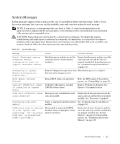
...action. Damage due to servicing that they are installed. faulty memory module(s). Ensure that all pairs of memory modules are of the same type and size and that is not authorized by Dell is not covered by your product documentation, or as authorized in... is installed on page 102. System Messages Message Causes Corrective Actions Alert! Memory configuration does not support redundant memory. Installed memory modules are not the same type and size; Attempting to update Remote Configuration. Please wait... Retry the BIOS update. If the problem persists, see ...
...action. Damage due to servicing that they are installed. faulty memory module(s). Ensure that all pairs of memory modules are of the same type and size and that is not authorized by Dell is not covered by your product documentation, or as authorized in... is installed on page 102. System Messages Message Causes Corrective Actions Alert! Memory configuration does not support redundant memory. Installed memory modules are not the same type and size; Attempting to update Remote Configuration. Please wait... Retry the BIOS update. If the problem persists, see ...

Hardware Owner's Manual (PDF)
Page 26
... compatibility. Error: Incorrect memory configuration. DIMMs must be populated in sequential order beginning with slot 1. See "System Memory" on page 71. See "RAC Card" on page 63. memory upgrade kits directly from www.dell.com or your Dell sales agent to its ... by BIOS: DIMM x Rank y Mismatched DIMMs installed; Faulty or improperly seated memory See "Troubleshooting System Memory" module(s). is contains DIMMs that they memory module(s). Dell recommends purchasing with slot 1. System Messages (continued) Message Causes Corrective Actions DIMMs must...
... compatibility. Error: Incorrect memory configuration. DIMMs must be populated in sequential order beginning with slot 1. See "System Memory" on page 71. See "RAC Card" on page 63. memory upgrade kits directly from www.dell.com or your Dell sales agent to its ... by BIOS: DIMM x Rank y Mismatched DIMMs installed; Faulty or improperly seated memory See "Troubleshooting System Memory" module(s). is contains DIMMs that they memory module(s). Dell recommends purchasing with slot 1. System Messages (continued) Message Causes Corrective Actions DIMMs must...

Hardware Owner's Manual (PDF)
Page 64
... entire capacity of the four DIMMs is allocated to the preceding installation guidelines. Non-Optimal Memory Configurations System performance can be affected if your memory configuration does not conform to sparing whereas for dual-rank DIMMs, only half of two memory module sockets: • Channel 0 contains DIMM_1, DIMM_5. • Channel 1 contains DIMM _2, DIMM_6. •...
... entire capacity of the four DIMMs is allocated to the preceding installation guidelines. Non-Optimal Memory Configurations System performance can be affected if your memory configuration does not conform to sparing whereas for dual-rank DIMMs, only half of two memory module sockets: • Channel 0 contains DIMM_1, DIMM_5. • Channel 1 contains DIMM _2, DIMM_6. •...


