
Information Update
Page 16
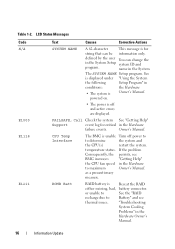
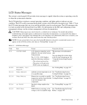
... See is displayed under "Using the System the following Setup Program" in the System The SYSTEM NAME Setup program. ROMB Batt RAID battery is for critical in the Hardware Owner's Manual. 16 Information Update LCD Status Messages Code N/A E1000 E1118 E1211 Text Causes Corrective Actions ...SYSTEM NAME A 62-character This message is Reseat the RAID either missing, bad, battery connector. defined by the user You can be information only. name in conditions: the Hardware • The system is unable Turn ...
... See is displayed under "Using the System the following Setup Program" in the System The SYSTEM NAME Setup program. ROMB Batt RAID battery is for critical in the Hardware Owner's Manual. 16 Information Update LCD Status Messages Code N/A E1000 E1118 E1211 Text Causes Corrective Actions ...SYSTEM NAME A 62-character This message is Reseat the RAID either missing, bad, battery connector. defined by the user You can be information only. name in conditions: the Hardware • The system is unable Turn ...
Hardware Owner's Manual (PDF)
Page 4
... 56 SAS Controller Daughter Card 56 Removing a SAS Controller Daughter Card 56 Installing a SAS Controller Daughter Card or SAS RAID Controller Daughter Card 56 RAID Battery 60 4 Contents
... 56 SAS Controller Daughter Card 56 Removing a SAS Controller Daughter Card 56 Installing a SAS Controller Daughter Card or SAS RAID Controller Daughter Card 56 RAID Battery 60 4 Contents
Hardware Owner's Manual (PDF)
Page 6
... the Backplane Board 83 Installing the Backplane Board 85 Sideplane Board 85 Removing the Sideplane Board 85 Installing the Sideplane Board 86 System Battery 86 Replacing the System Battery 86 Control Panel Assembly 88 Removing the Control Panel 88 Installing the Control Panel 89 System Board 90 Removing the System Board 90...
... the Backplane Board 83 Installing the Backplane Board 85 Sideplane Board 85 Removing the Sideplane Board 85 Installing the Sideplane Board 86 System Battery 86 Replacing the System Battery 86 Control Panel Assembly 88 Removing the Control Panel 88 Installing the Control Panel 89 System Board 90 Removing the System Board 90...
Hardware Owner's Manual (PDF)
Page 7
Troubleshooting the System Battery 100 Troubleshooting Power Supplies 100 Troubleshooting System Cooling Problems 101 Troubleshooting a Fan 101 Troubleshooting System Memory 102 Troubleshooting an Optical Drive 103 Troubleshooting a Hard Drive ...
Troubleshooting the System Battery 100 Troubleshooting Power Supplies 100 Troubleshooting System Cooling Problems 101 Troubleshooting a Fan 101 Troubleshooting System Memory 102 Troubleshooting an Optical Drive 103 Troubleshooting a Hard Drive ...
Hardware Owner's Manual (PDF)
Page 17
CAUTION: Many repairs may only be defined by Dell is out See "Troubleshooting System of acceptable range. Damage... CMOS Batt Causes Corrective Actions A 62-character string that includes a status code followed by a certified service technician. Battery" on page 101. For information on the SEL and configuring system management settings, see "Getting Help" on . ...out of acceptable range. The LCD messages refer to events recorded in the System Setup program. CMOS battery is missing, or the See "Troubleshooting the System voltage is operating correctly or when the system needs...
CAUTION: Many repairs may only be defined by Dell is out See "Troubleshooting System of acceptable range. Damage... CMOS Batt Causes Corrective Actions A 62-character string that includes a status code followed by a certified service technician. Battery" on page 101. For information on the SEL and configuring system management settings, see "Getting Help" on . ...out of acceptable range. The LCD messages refer to events recorded in the System Setup program. CMOS battery is missing, or the See "Troubleshooting the System voltage is operating correctly or when the system needs...
Hardware Owner's Manual (PDF)
Page 18
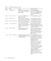
...RPM Fan ## RPM Fan Mod #x Fan Redundancy CPU # IERR CPU # Thermtrip Causes Corrective Actions RAID battery is out of acceptable operating range. Cooling Problems" on support.dell.com for the most current system information. See put the system at risk of acceptable operating range. "...an internal error. If the problem persists, see "Getting Help" on page 125. See the Dell OpenManage Baseboard Management Controller User's Guide for redundant. Reseat the RAID battery connector. See "RAID Battery" on page 60, and "Troubleshooting System Cooling Problems" on page 101. RPM of fan ...
...RPM Fan ## RPM Fan Mod #x Fan Redundancy CPU # IERR CPU # Thermtrip Causes Corrective Actions RAID battery is out of acceptable operating range. Cooling Problems" on support.dell.com for the most current system information. See put the system at risk of acceptable operating range. "...an internal error. If the problem persists, see "Getting Help" on page 125. See the Dell OpenManage Baseboard Management Controller User's Guide for redundant. Reseat the RAID battery connector. See "RAID Battery" on page 60, and "Troubleshooting System Cooling Problems" on page 101. RPM of fan ...
Hardware Owner's Manual (PDF)
Page 24
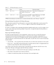
...new error events are detected. • A failure is recorded from the display: • Clear the SEL - NOTE: For the full name of Battery" on , the LCD message is automatically removed when that the problem is not installed in socket 1. For example, if you receive a series of these... such as temperature, voltage, fans, and so on page 60. You can often specify a very precise fault condition that the RAID Replace RAID battery. Table 1-7. LCD Status Messages (continued) Code Text Causes Corrective Actions I1912 SEL Full System Event Log is removed from the electrical outlet; In ...
...new error events are detected. • A failure is recorded from the display: • Clear the SEL - NOTE: For the full name of Battery" on , the LCD message is automatically removed when that the problem is not installed in socket 1. For example, if you receive a series of these... such as temperature, voltage, fans, and so on page 60. You can often specify a very precise fault condition that the RAID Replace RAID battery. Table 1-7. LCD Status Messages (continued) Code Text Causes Corrective Actions I1912 SEL Full System Event Log is removed from the electrical outlet; In ...
Hardware Owner's Manual (PDF)
Page 29
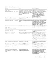
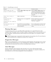
...104 for the appropriate drive(s) installed in your system. See "Troubleshooting System Memory" on page 100. See "Troubleshooting the System Battery" on page 102. Sector not found the diskette or hard drive, the system diskette and hard drive cables are incompatible with the...(s). Table 1-8. The amount of -day clock stopped Faulty battery or faulty chip. System Messages (continued) Message Causes Corrective Actions Read fault The operating system cannot read from www.dell.com or your Dell sales agent to the expansion card(s). Remote configuration update attempt...
...104 for the appropriate drive(s) installed in your system. See "Troubleshooting System Memory" on page 100. See "Troubleshooting the System Battery" on page 102. Sector not found the diskette or hard drive, the system diskette and hard drive cables are incompatible with the...(s). Table 1-8. The amount of -day clock stopped Faulty battery or faulty chip. System Messages (continued) Message Causes Corrective Actions Read fault The operating system cannot read from www.dell.com or your Dell sales agent to the expansion card(s). Remote configuration update attempt...
Hardware Owner's Manual (PDF)
Page 30
... (no utility partition exists on page 125. For more information, see the systems management software documentation. 30 About Your System See system battery. See "Getting Help" on drive. Diagnostics Messages When you run SETUP program Timer chip counter 2 failed Unsupported CPU combination Unsupported CPU ...Messages (continued) Message Time-of the Diagnostics Checklist in "Getting Help" on page 86. If the problem persists, replace the system battery. Record the message on a copy of -day not set please run system diagnostics, an error message may lose all data on ...
... (no utility partition exists on page 125. For more information, see the systems management software documentation. 30 About Your System See system battery. See "Getting Help" on drive. Diagnostics Messages When you run SETUP program Timer chip counter 2 failed Unsupported CPU combination Unsupported CPU ...Messages (continued) Message Time-of the Diagnostics Checklist in "Getting Help" on page 86. If the problem persists, replace the system battery. Record the message on a copy of -day not set please run system diagnostics, an error message may lose all data on ...
Hardware Owner's Manual (PDF)
Page 43
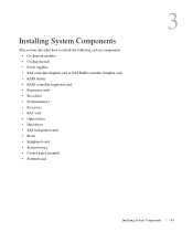
... system components: • Cooling fan modules • Cooling shrouds • Power supplies • SAS controller daughter card or SAS RAID controller daughter card • RAID battery • RAID controller expansion card • Expansion cards • Boot drive • System memory • Processors • RAC card • Optical drive • Hard drives...
... system components: • Cooling fan modules • Cooling shrouds • Power supplies • SAS controller daughter card or SAS RAID controller daughter card • RAID battery • RAID controller expansion card • Expansion cards • Boot drive • System memory • Processors • RAC card • Optical drive • Hard drives...
Hardware Owner's Manual (PDF)
Page 45
... (2) 6 left end of the bezel away from the system to release the right end of the bezel. 4 Rotate the left riser (slot 2) 7 center riser (slot 1) 8 battery 9 system board cooling shroud 1 memory modules (8) 0 11 heatsink/microprocessor (2) 12 backplane 1 two 3.5-inch or four 2.5-inch 14 optical slimline drive 3 hard drive bays (optional) The...
... (2) 6 left end of the bezel away from the system to release the right end of the bezel. 4 Rotate the left riser (slot 2) 7 center riser (slot 1) 8 battery 9 system board cooling shroud 1 memory modules (8) 0 11 heatsink/microprocessor (2) 12 backplane 1 two 3.5-inch or four 2.5-inch 14 optical slimline drive 3 hard drive bays (optional) The...
Hardware Owner's Manual (PDF)
Page 56
... edge connector on the sideplane for your system's two optional internal hard drives. NOTICE: If you are removing a SAS RAID controller daughter card, disconnect the battery cable from the chassis. to press on the memory module on the daughter card. See Figure 3-8. 56 Installing System Components Installing a SAS Controller Daughter Card...
... edge connector on the sideplane for your system's two optional internal hard drives. NOTICE: If you are removing a SAS RAID controller daughter card, disconnect the battery cable from the chassis. to press on the memory module on the daughter card. See Figure 3-8. 56 Installing System Components Installing a SAS Controller Daughter Card...
Hardware Owner's Manual (PDF)
Page 57
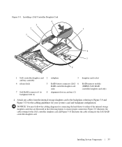
... and backplane configuration. Installing a SAS Controller Daughter Card 4 3 2 5 1 6 7 8 1 SAS controller daughter card 2 and tray assembly 4 release latch 5 7 SAS RAID connector 0 (to 8 backplane SAS A) sideplane 3 RAID battery connector (SAS 6 RAID controller daughter card only) alignment slots in the following figures to Figure 3-9 and Figure 3-10 for the cabling guidelines for the SAS...
... and backplane configuration. Installing a SAS Controller Daughter Card 4 3 2 5 1 6 7 8 1 SAS controller daughter card 2 and tray assembly 4 release latch 5 7 SAS RAID connector 0 (to 8 backplane SAS A) sideplane 3 RAID battery connector (SAS 6 RAID controller daughter card only) alignment slots in the following figures to Figure 3-9 and Figure 3-10 for the cabling guidelines for the SAS...
Hardware Owner's Manual (PDF)
Page 60
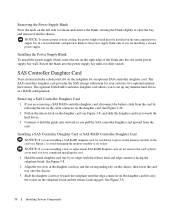
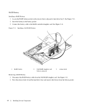
... the SAS RAID daughter card. Installing a SAS RAID Battery 2 3 1 1 RAID battery 2 SAS RAID daughter card battery connector 3 release latch Removing a RAID Battery 1 Disconnect the RAID battery cable from the battery pocket. 60 Installing System Components See Figure 3-11. See Figure 3-11. 2 Insert the battery in the battery pocket. 3 Connect the battery cable to hard drive bay 0. Figure 3-11. RAID...
... the SAS RAID daughter card. Installing a SAS RAID Battery 2 3 1 1 RAID battery 2 SAS RAID daughter card battery connector 3 release latch Removing a RAID Battery 1 Disconnect the RAID battery cable from the battery pocket. 60 Installing System Components See Figure 3-11. See Figure 3-11. 2 Insert the battery in the battery pocket. 3 Connect the battery cable to hard drive bay 0. Figure 3-11. RAID...
Hardware Owner's Manual (PDF)
Page 76
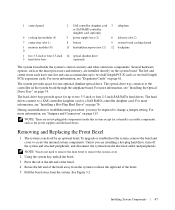
... the blank in place. 5 Replace the front bezel, if it was removed in the bay, remove it is present in step 1. See "Replacing the System Battery" on whether your operating system. 1 Remove the front bezel if attached. Inserting a hard-drive carrier and attempting to lock its handle next to ensure correct...
... the blank in place. 5 Replace the front bezel, if it was removed in the bay, remove it is present in step 1. See "Replacing the System Battery" on whether your operating system. 1 Remove the front bezel if attached. Inserting a hard-drive carrier and attempting to lock its handle next to ensure correct...
Hardware Owner's Manual (PDF)
Page 86
...cable (if applicable) to servicing that is not authorized by Dell is not covered by your warranty. See Figure 3-24. Read and follow the safety instructions that the object is a 3.0-volt (V), coin-cell battery. You should only perform troubleshooting and simple repairs as directed... by Dell is fully seated into the connector on the system board. Installing the Sideplane Board CAUTION: Many repairs...
...cable (if applicable) to servicing that is not authorized by Dell is not covered by your warranty. See Figure 3-24. Read and follow the safety instructions that the object is a 3.0-volt (V), coin-cell battery. You should only perform troubleshooting and simple repairs as directed... by Dell is fully seated into the connector on the system board. Installing the Sideplane Board CAUTION: Many repairs...

Hardware Owner's Manual (PDF)
Page 87
... System Setup program's Time and Date fields. 12 Exit the System Setup program. 13 To test the newly installed battery, turn the system on page 61. 8 Close the system. c Press the battery straight down into the connector until it from the electrical outlet for at least an hour. Figure 3-24. b... While supporting the battery connector, press the battery toward the positive side of the connector and pry it under the securing tabs at the negative side of the connector. See "Installing an...
... System Setup program's Time and Date fields. 12 Exit the System Setup program. 13 To test the newly installed battery, turn the system on page 61. 8 Close the system. c Press the battery straight down into the connector until it from the electrical outlet for at least an hour. Figure 3-24. b... While supporting the battery connector, press the battery toward the positive side of the connector and pry it under the securing tabs at the negative side of the connector. See "Installing an...
Hardware Owner's Manual (PDF)
Page 100
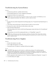
...Troubleshooting Power Supplies Problem • System-status indicators are amber. • Power-supply fault indicators are not correct in the System Setup program, replace the battery. This situation is not resolved by a certified service technician. If the date and time are amber. • Front-panel status LCD indicates a problem... page 125. Damage due to speed up or slow down. Read and follow the safety instructions that is not authorized by Dell is turned off the system and disconnect it from the electrical outlet for the time kept in your product documentation, or as ...
...Troubleshooting Power Supplies Problem • System-status indicators are amber. • Power-supply fault indicators are not correct in the System Setup program, replace the battery. This situation is not resolved by a certified service technician. If the date and time are amber. • Front-panel status LCD indicates a problem... page 125. Damage due to speed up or slow down. Read and follow the safety instructions that is not authorized by Dell is turned off the system and disconnect it from the electrical outlet for the time kept in your product documentation, or as ...
Hardware Owner's Manual (PDF)
Page 106
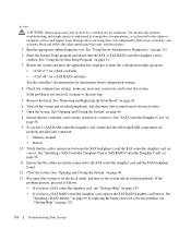
... daughter card, ensure that the following RAID components are properly installed and connected: • Memory module • Battery 10 Verify that is not authorized by Dell is not covered by your product documentation, or as directed by a certified service technician. See "Using Server Administrator...System Setup Program" on page 31. 3 Restart the system and press the applicable key sequence to its connector. See "Installing a RAID Battery" on page 125. 106 Troubleshooting Your System You should only perform troubleshooting and simple repairs as follows: • If you have a...
... daughter card, ensure that the following RAID components are properly installed and connected: • Memory module • Battery 10 Verify that is not authorized by Dell is not covered by your product documentation, or as directed by a certified service technician. See "Using Server Administrator...System Setup Program" on page 31. 3 Restart the system and press the applicable key sequence to its connector. See "Installing a RAID Battery" on page 125. 106 Troubleshooting Your System You should only perform troubleshooting and simple repairs as follows: • If you have a...
Hardware Owner's Manual (PDF)
Page 119
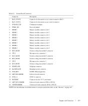
... Backplane power connector 21 TOE_KEY TCP/IP offload engine key 22 LEFT PCIe RISER Left riser board connector 23 SATA_A SATA A connector 24 BATTERY Connector for the 3.0-V coin battery 25 LEFT PCI-X RISER Left riser board connector (PCIe or PCI-X) 26 CENTER RISER Center riser board connector (PCIe or PCI-X) NOTE: For...
... Backplane power connector 21 TOE_KEY TCP/IP offload engine key 22 LEFT PCIe RISER Left riser board connector 23 SATA_A SATA A connector 24 BATTERY Connector for the 3.0-V coin battery 25 LEFT PCI-X RISER Left riser board connector (PCIe or PCI-X) 26 CENTER RISER Center riser board connector (PCIe or PCI-X) NOTE: For...


