
Information Update
Page 16
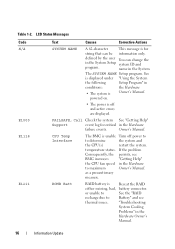
.... CPU Temp Interface The BMC is Owner's Manual. name in the Hardware Owner's Manual. 16 Information Update ROMB Batt RAID battery is off power to to Battery" and see BMC increases "Getting Help" the CPU fan speed in the Hardware failure events. If the problem Consequently, the ... is unable Turn off and active errors are displayed. powered on. • The power is Reseat the RAID either missing, bad, battery connector. "Troubleshooting System Cooling Problems" in the System The SYSTEM NAME Setup program. defined by the user You can be information only.
.... CPU Temp Interface The BMC is Owner's Manual. name in the Hardware Owner's Manual. 16 Information Update ROMB Batt RAID battery is off power to to Battery" and see BMC increases "Getting Help" the CPU fan speed in the Hardware failure events. If the problem Consequently, the ... is unable Turn off and active errors are displayed. powered on. • The power is Reseat the RAID either missing, bad, battery connector. "Troubleshooting System Cooling Problems" in the System The SYSTEM NAME Setup program. defined by the user You can be information only.
Hardware Owner's Manual (PDF)
Page 4
... 56 SAS Controller Daughter Card 56 Removing a SAS Controller Daughter Card 56 Installing a SAS Controller Daughter Card or SAS RAID Controller Daughter Card 56 RAID Battery 60 4 Contents
... 56 SAS Controller Daughter Card 56 Removing a SAS Controller Daughter Card 56 Installing a SAS Controller Daughter Card or SAS RAID Controller Daughter Card 56 RAID Battery 60 4 Contents
Hardware Owner's Manual (PDF)
Page 6
... the Backplane Board 83 Installing the Backplane Board 85 Sideplane Board 85 Removing the Sideplane Board 85 Installing the Sideplane Board 86 System Battery 86 Replacing the System Battery 86 Control Panel Assembly 88 Removing the Control Panel 88 Installing the Control Panel 89 System Board 90 Removing the System Board 90...
... the Backplane Board 83 Installing the Backplane Board 85 Sideplane Board 85 Removing the Sideplane Board 85 Installing the Sideplane Board 86 System Battery 86 Replacing the System Battery 86 Control Panel Assembly 88 Removing the Control Panel 88 Installing the Control Panel 89 System Board 90 Removing the System Board 90...
Hardware Owner's Manual (PDF)
Page 7
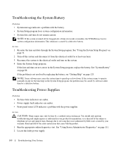
Troubleshooting the System Battery 100 Troubleshooting Power Supplies 100 Troubleshooting System Cooling Problems 101 Troubleshooting a Fan 101 Troubleshooting System Memory 102 Troubleshooting an Optical Drive 103 Troubleshooting a Hard Drive ...
Troubleshooting the System Battery 100 Troubleshooting Power Supplies 100 Troubleshooting System Cooling Problems 101 Troubleshooting a Fan 101 Troubleshooting System Memory 102 Troubleshooting an Optical Drive 103 Troubleshooting a Hard Drive ...
Hardware Owner's Manual (PDF)
Page 17
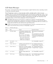
...LCD status messages that came with the product. The LCD messages refer to events recorded in your product documentation, or as directed by Dell is out See "Troubleshooting System of acceptable range. Read and follow the safety instructions that can occur and the probable cause for each...E12nn xx PwrGd E1210 CMOS Batt Causes Corrective Actions A 62-character string that can change the system string in the System Setup program. Battery" on page 101. NOTE: If your warranty. This message is operating correctly or when the system needs attention. Ambient system temperature is...
...LCD status messages that came with the product. The LCD messages refer to events recorded in your product documentation, or as directed by Dell is out See "Troubleshooting System of acceptable range. Read and follow the safety instructions that can occur and the probable cause for each...E12nn xx PwrGd E1210 CMOS Batt Causes Corrective Actions A 62-character string that can change the system string in the System Setup program. Battery" on page 101. NOTE: If your warranty. This message is operating correctly or when the system needs attention. Ambient system temperature is...
Hardware Owner's Manual (PDF)
Page 18
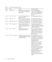
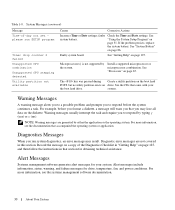
...: The LCD continues to display this message until the system's power cord is disconnected and reconnected to thermal issues. See "RAID Battery" on page 60, and "Troubleshooting System Cooling Problems" on page 101. Check control panel LCD for information about these utilities. 18... of acceptable operating range. See your system's "Information Update Tech Sheet" located on page 125. Reseat the RAID battery connector. See "Getting Help" on support.dell.com for the most current system information. See put the system at risk of acceptable operating range. Cooling Problems"...
...: The LCD continues to display this message until the system's power cord is disconnected and reconnected to thermal issues. See "RAID Battery" on page 60, and "Troubleshooting System Cooling Problems" on page 101. Check control panel LCD for information about these utilities. 18... of acceptable operating range. See your system's "Information Update Tech Sheet" located on page 125. Reseat the RAID battery connector. See "Getting Help" on support.dell.com for the most current system information. See put the system at risk of acceptable operating range. Cooling Problems"...
Hardware Owner's Manual (PDF)
Page 24
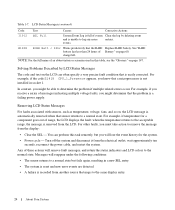
... for the system. • Power cycle - wait approximately ten seconds, reconnect the power cable, and restart the system. For example, if you receive a series of Battery" on the LCD can perform this table, see the "Glossary" on , the LCD message is unable to a normal state. For other faults, you might be... log by LCD Status Messages The code and text on page 60. You can often specify a very precise fault condition that the RAID Replace RAID battery. NOTE: For the full name of an abbreviation or acronym used in a new SEL entry. • The system is reset and new error events ...
... for the system. • Power cycle - wait approximately ten seconds, reconnect the power cable, and restart the system. For example, if you receive a series of Battery" on the LCD can perform this table, see the "Glossary" on , the LCD message is unable to a normal state. For other faults, you might be... log by LCD Status Messages The code and text on page 60. You can often specify a very precise fault condition that the RAID Replace RAID battery. NOTE: For the full name of an abbreviation or acronym used in a new SEL entry. • The system is reset and new error events ...
Hardware Owner's Manual (PDF)
Page 29
... are properly could not find a particular sector on page 107, or defective. Dell recommends purchasing memory upgrade kits directly from www.dell.com or your Dell sales agent to ensure compatibility. Dell recommends purchasing memory upgrade kits directly from Replace the diskette. About Your System 29...on page 107. If the problem persists, see "Troubleshooting Expansion Cards" on page 102. The amount of -day clock stopped Faulty battery or faulty chip. See "Troubleshooting disk, or the requested sector is informative and can be faulty. Ensure that only ECC FBD1 memory...
... are properly could not find a particular sector on page 107, or defective. Dell recommends purchasing memory upgrade kits directly from www.dell.com or your Dell sales agent to ensure compatibility. Dell recommends purchasing memory upgrade kits directly from Replace the diskette. About Your System 29...on page 107. If the problem persists, see "Troubleshooting Expansion Cards" on page 102. The amount of -day clock stopped Faulty battery or faulty chip. See "Troubleshooting disk, or the requested sector is informative and can be faulty. Ensure that only ECC FBD1 memory...
Hardware Owner's Manual (PDF)
Page 30
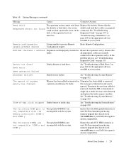
...Message Time-of the Diagnostics Checklist in "Getting Help" on page 125, and then follow the instructions in this section. See system battery. Microprocessor(s) is not supported by typing y (yes) or n (no utility partition exists on the diskette. microprocessor combination. system... to respond before you format a diskette, a message will warn you may result. If the problem persists, replace the system battery. For more information, see the documentation that section for drive, temperature, fan, and power conditions. Table 1-8. Alert messages include...
...Message Time-of the Diagnostics Checklist in "Getting Help" on page 125, and then follow the instructions in this section. See system battery. Microprocessor(s) is not supported by typing y (yes) or n (no utility partition exists on the diskette. microprocessor combination. system... to respond before you format a diskette, a message will warn you may result. If the problem persists, replace the system battery. For more information, see the documentation that section for drive, temperature, fan, and power conditions. Table 1-8. Alert messages include...
Hardware Owner's Manual (PDF)
Page 43
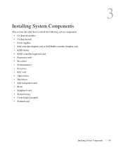
... system components: • Cooling fan modules • Cooling shrouds • Power supplies • SAS controller daughter card or SAS RAID controller daughter card • RAID battery • RAID controller expansion card • Expansion cards • Boot drive • System memory • Processors • RAC card • Optical drive • Hard drives...
... system components: • Cooling fan modules • Cooling shrouds • Power supplies • SAS controller daughter card or SAS RAID controller daughter card • RAID battery • RAID controller expansion card • Expansion cards • Boot drive • System memory • Processors • RAC card • Optical drive • Hard drives...
Hardware Owner's Manual (PDF)
Page 45
... panel 2 SAS controller daughter card 3 sideplane or SAS RAID controller daughter card (optional) 4 cooling fan modules (4) 5 power supply bays (2) 6 left riser (slot 2) 7 center riser (slot 1) 8 battery 9 system board cooling shroud 1 memory modules (8) 0 11 heatsink/microprocessor (2) 12 backplane 1 two 3.5-inch or four 2.5-inch 14 optical slimline drive 3 hard drive bays (optional) The...
... panel 2 SAS controller daughter card 3 sideplane or SAS RAID controller daughter card (optional) 4 cooling fan modules (4) 5 power supply bays (2) 6 left riser (slot 2) 7 center riser (slot 1) 8 battery 9 system board cooling shroud 1 memory modules (8) 0 11 heatsink/microprocessor (2) 12 backplane 1 two 3.5-inch or four 2.5-inch 14 optical slimline drive 3 hard drive bays (optional) The...
Hardware Owner's Manual (PDF)
Page 56
... into the socket on the daughter card. The optional SAS RAID controller daughter card allows you are removing a SAS RAID controller daughter card, disconnect the battery cable from the chassis. NOTICE: If you have completed installing the card. 1 Hold the metal daughter card tray by releasing the tab on the cable...
... into the socket on the daughter card. The optional SAS RAID controller daughter card allows you are removing a SAS RAID controller daughter card, disconnect the battery cable from the chassis. NOTICE: If you have completed installing the card. 1 Hold the metal daughter card tray by releasing the tab on the cable...
Hardware Owner's Manual (PDF)
Page 57
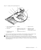
... and backplane configuration. Installing a SAS Controller Daughter Card 4 3 2 5 1 6 7 8 1 SAS controller daughter card 2 and tray assembly 4 release latch 5 7 SAS RAID connector 0 (to 8 backplane SAS A) sideplane 3 RAID battery connector (SAS 6 RAID controller daughter card only) alignment slots in the following figures to Figure 3-9 and Figure 3-10 for the cabling guidelines for the SAS...
... and backplane configuration. Installing a SAS Controller Daughter Card 4 3 2 5 1 6 7 8 1 SAS controller daughter card 2 and tray assembly 4 release latch 5 7 SAS RAID connector 0 (to 8 backplane SAS A) sideplane 3 RAID battery connector (SAS 6 RAID controller daughter card only) alignment slots in the following figures to Figure 3-9 and Figure 3-10 for the cabling guidelines for the SAS...
Hardware Owner's Manual (PDF)
Page 60
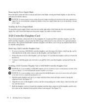
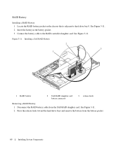
Installing a SAS RAID Battery 2 3 1 1 RAID battery 2 SAS RAID daughter card battery connector 3 release latch Removing a RAID Battery 1 Disconnect the RAID battery cable from the battery pocket. 60 Installing System Components RAID Battery Installing a RAID Battery 1 Locate the RAID battery pocket on the chassis that is adjacent to the RAID controller daughter card. See Figure 3-11. 2 Press the release latch toward...
Installing a SAS RAID Battery 2 3 1 1 RAID battery 2 SAS RAID daughter card battery connector 3 release latch Removing a RAID Battery 1 Disconnect the RAID battery cable from the battery pocket. 60 Installing System Components RAID Battery Installing a RAID Battery 1 Locate the RAID battery pocket on the chassis that is adjacent to the RAID controller daughter card. See Figure 3-11. 2 Press the release latch toward...
Hardware Owner's Manual (PDF)
Page 76
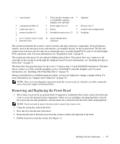
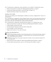
... its handle next to release the blank. See "Removing and Replacing the Front Bezel" on page 75. 76 Installing System Components See "Replacing the System Battery" on whether your operating system. 1 Remove the front bezel if attached.
... its handle next to release the blank. See "Removing and Replacing the Front Bezel" on page 75. 76 Installing System Components See "Replacing the System Battery" on whether your operating system. 1 Remove the front bezel if attached.
Hardware Owner's Manual (PDF)
Page 86
... system battery is incorrectly installed. Read and follow the safety instructions that came with the pins on the system board, and lower the sideplane until that is not authorized by Dell is installed in your System Information Guide for additional information. 1 Turn off the socket or... by the online or telephone service and support team. Ensure that came with the product. 1 Align the guide on the end of a new battery exploding if it is ...
... system battery is incorrectly installed. Read and follow the safety instructions that came with the pins on the system board, and lower the sideplane until that is not authorized by Dell is installed in your System Information Guide for additional information. 1 Turn off the socket or... by the online or telephone service and support team. Ensure that came with the product. 1 Align the guide on the end of a new battery exploding if it is ...

Hardware Owner's Manual (PDF)
Page 87
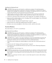
... place. 7 If you must firmly support the connector while installing or removing a battery. 6 Install the new system battery. Replacing the System Battery 1 2 3 1 positive side of battery connector 2 system battery 3 negative side of battery connector NOTICE: To avoid damage to its electrical outlet and turn off the system ... the negative side of the connector. See "Opening and Closing the System" on page 46. 9 Reconnect the system to the battery connector, you removed an expansion card in the System Setup program's Time and Date fields. 12 Exit the System Setup program....
... place. 7 If you must firmly support the connector while installing or removing a battery. 6 Install the new system battery. Replacing the System Battery 1 2 3 1 positive side of battery connector 2 system battery 3 negative side of battery connector NOTICE: To avoid damage to its electrical outlet and turn off the system ... the negative side of the connector. See "Opening and Closing the System" on page 46. 9 Reconnect the system to the battery connector, you removed an expansion card in the System Setup program's Time and Date fields. 12 Exit the System Setup program....
Hardware Owner's Manual (PDF)
Page 100
...team. NOTE: Some software may only be caused by software rather than by your product documentation, or as directed by a defective battery. See "System Battery" on page 111. 2 Locate the faulty power supply. 100 Troubleshooting Your System If the system seems to the electrical outlet and... information. This situation is not resolved by a certified service technician. Read and follow the safety instructions that is not authorized by Dell is turned off the system and disconnect it from the electrical outlet for at least one hour. 3 Reconnect the system to operate...
...team. NOTE: Some software may only be caused by software rather than by your product documentation, or as directed by a defective battery. See "System Battery" on page 111. 2 Locate the faulty power supply. 100 Troubleshooting Your System If the system seems to the electrical outlet and... information. This situation is not resolved by a certified service technician. Read and follow the safety instructions that is not authorized by Dell is turned off the system and disconnect it from the electrical outlet for at least one hour. 3 Reconnect the system to operate...
Hardware Owner's Manual (PDF)
Page 106
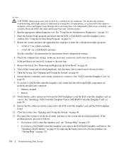
...If the problem is not covered by the online or telephone service and support team. Action CAUTION: Many repairs may only be done by Dell is not resolved, continue to the next step. 5 Remove the bezel. See "Using the System Setup Program" on page 60. See... that the cable connections between the SAS backplane(s) and the SAS controller daughter card are properly installed and connected: • Memory module • Battery 10 Verify that is not authorized by a certified service technician. Damage due to enter the configuration utility program: • for a SAS controller ...
...If the problem is not covered by the online or telephone service and support team. Action CAUTION: Many repairs may only be done by Dell is not resolved, continue to the next step. 5 Remove the bezel. See "Using the System Setup Program" on page 60. See... that the cable connections between the SAS backplane(s) and the SAS controller daughter card are properly installed and connected: • Memory module • Battery 10 Verify that is not authorized by a certified service technician. Damage due to enter the configuration utility program: • for a SAS controller ...
Hardware Owner's Manual (PDF)
Page 119
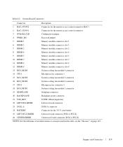
... Backplane power connector 21 TOE_KEY TCP/IP offload engine key 22 LEFT PCIe RISER Left riser board connector 23 SATA_A SATA A connector 24 BATTERY Connector for the 3.0-V coin battery 25 LEFT PCI-X RISER Left riser board connector (PCIe or PCI-X) 26 CENTER RISER Center riser board connector (PCIe or PCI-X) NOTE: For...
... Backplane power connector 21 TOE_KEY TCP/IP offload engine key 22 LEFT PCIe RISER Left riser board connector 23 SATA_A SATA A connector 24 BATTERY Connector for the 3.0-V coin battery 25 LEFT PCI-X RISER Left riser board connector (PCIe or PCI-X) 26 CENTER RISER Center riser board connector (PCIe or PCI-X) NOTE: For...


