
User's Guide
Page 3
Contents 1 Introduction 9 System Description 9 PowerConnect 2808 9 PowerConnect 2816 9 PowerConnect 2824 10 PowerConnect 2848 10 Summary of PowerConnect Models 11 Features 11 General Features 11 MAC Address Supported Features 13 Layer 2 Features 13 VLAN Supported Features 14 Spanning Tree Protocol Features 15 Class of Service (CoS) Features 16 Ethernet Switch Management Features 16 2 Hardware Description 17 Switch Port Configurations 17...
Contents 1 Introduction 9 System Description 9 PowerConnect 2808 9 PowerConnect 2816 9 PowerConnect 2824 10 PowerConnect 2848 10 Summary of PowerConnect Models 11 Features 11 General Features 11 MAC Address Supported Features 13 Layer 2 Features 13 VLAN Supported Features 14 Spanning Tree Protocol Features 15 Class of Service (CoS) Features 16 Ethernet Switch Management Features 16 2 Hardware Description 17 Switch Port Configurations 17...
User's Guide
Page 7
... 126 VLAN Port Membership Table 128 Defining VLAN Ports Settings 130 Defining VLAN LAG Settings 131 Aggregating Ports 133 Defining LAG Membership 134 Multicast Forwarding Support 134 Defining Multicast Global Parameters 135 Adding Bridge Multicast Address Members 136 Assigning Multicast Forward All Parameters 138 IGMP Snooping 141 8 Viewing Statistics 143 Viewing...
... 126 VLAN Port Membership Table 128 Defining VLAN Ports Settings 130 Defining VLAN LAG Settings 131 Aggregating Ports 133 Defining LAG Membership 134 Multicast Forwarding Support 134 Defining Multicast Global Parameters 135 Adding Bridge Multicast Address Members 136 Assigning Multicast Forward All Parameters 138 IGMP Snooping 141 8 Viewing Statistics 143 Viewing...

User's Guide
Page 8
... Command: interface vlan 166 Command: ip address 166 Command: ip default-gateway 167 Command: login 167 Command: ping 167 Commad: reload 169 Command: show tech-support command 169 Command: snmp-server community 171 Command: username 172 Glossary 173 Index 183 8 Contents
... Command: interface vlan 166 Command: ip address 166 Command: ip default-gateway 167 Command: login 167 Command: ping 167 Commad: reload 169 Command: show tech-support command 169 Command: snmp-server community 171 Command: username 172 Glossary 173 Index 183 8 Contents

User's Guide
Page 9
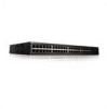
... traffic control. Dell PowerConnect 28xx Systems User Guide 9 The PowerConnect management features are managed by Dell's OpenManage Switch Administrator. The switches are designed to medium business that require high performance edge connectivity. These PowerConnect devices are primarily designated for installing, configuring and maintaining the PowerConnect 2808, PowerConnect 2816, PowerConnect 2824, and PowerConnect 2848 Webmanaged Gigabit Ethernet switches. PowerConnect 2808 The following...
... traffic control. Dell PowerConnect 28xx Systems User Guide 9 The PowerConnect management features are managed by Dell's OpenManage Switch Administrator. The switches are designed to medium business that require high performance edge connectivity. These PowerConnect devices are primarily designated for installing, configuring and maintaining the PowerConnect 2808, PowerConnect 2816, PowerConnect 2824, and PowerConnect 2848 Webmanaged Gigabit Ethernet switches. PowerConnect 2808 The following...
User's Guide
Page 10
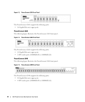
... Gigabit Ethernet copper ports • 2 SFP combo ports (1000BASE-SX or 1000BASE-LX) PowerConnect 2848 The following ports: • 48 Gigabit Ethernet copper ports • 4 SFP combo ports (1000BASE-SX or 1000BASE-LX) 10 Dell PowerConnect 28xx Systems User Guide PowerConnect 2816 Front Panel The PowerConnect 2816 supports the following ports: • 16 Gigabit Ethernet copper ports...
... Gigabit Ethernet copper ports • 2 SFP combo ports (1000BASE-SX or 1000BASE-LX) PowerConnect 2848 The following ports: • 48 Gigabit Ethernet copper ports • 4 SFP combo ports (1000BASE-SX or 1000BASE-LX) 10 Dell PowerConnect 28xx Systems User Guide PowerConnect 2816 Front Panel The PowerConnect 2816 supports the following ports: • 16 Gigabit Ethernet copper ports...

User's Guide
Page 11
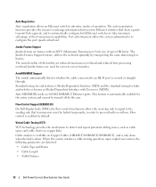
... Support On half-duplex links, the receiving port prevents buffer overflows by traffic competing for additional incoming traffic. Dell PowerConnect 28xx Systems User Guide 11 Provides switch management through the web interface. • Unmanaged Mode - PowerConnect Models Model PowerConnect 2808 PowerConnect 2816 PowerConnect 2824 PowerConnect 2848 ... port 1 External console port 2 Features General Features Management Modes The device supports the following table summarizes the PowerConnect models. Table 1-1. Fans baud rate is unavailable for the same egress port resources.
... Support On half-duplex links, the receiving port prevents buffer overflows by traffic competing for additional incoming traffic. Dell PowerConnect 28xx Systems User Guide 11 Provides switch management through the web interface. • Unmanaged Mode - PowerConnect Models Model PowerConnect 2808 PowerConnect 2816 PowerConnect 2824 PowerConnect 2848 ... port 1 External console port 2 Features General Features Management Modes The device supports the following table summarizes the PowerConnect models. Table 1-1. Fans baud rate is unavailable for the same egress port resources.
User's Guide
Page 12
...this facility are frames with Crossover (MDIX). The main benefits of their transmission capabilities. The Jumbo Frames Support feature, utilizes the network optimally by the user. Standard wiring for end stations is Media-Dependent Interface (... the mechanism to an RJ-45 port is down. This feature is enabled by default. AutoMDI/MDIX Support The switch automatically detects whether the cable connected to detect and report potential cabling issues, such as Media...Cable Type and Status • Cable Length • Fault-Distance 12 Dell PowerConnect 28xx Systems User Guide
...this facility are frames with Crossover (MDIX). The main benefits of their transmission capabilities. The Jumbo Frames Support feature, utilizes the network optimally by the user. Standard wiring for end stations is Media-Dependent Interface (... the mechanism to an RJ-45 port is down. This feature is enabled by default. AutoMDI/MDIX Support The switch automatically detects whether the cable connected to detect and report potential cabling issues, such as Media...Cable Type and Status • Cable Length • Fault-Distance 12 Dell PowerConnect 28xx Systems User Guide

User's Guide
Page 13
... relevant ports. IGMP Snooping is received for MAC Addresses MAC addresses from incoming packets. Dell PowerConnect 28xx Systems User Guide 13 MAC Address Supported Features MAC Address Capacity Support The PowerConnect 2808, 2816, 2824 switches support a total of 8K MAC addresses, and the PowerConnect 2848 supports a total of Ethernet connections. However, a similar functionality may be configured for information distribution...
... relevant ports. IGMP Snooping is received for MAC Addresses MAC addresses from incoming packets. Dell PowerConnect 28xx Systems User Guide 13 MAC Address Supported Features MAC Address Capacity Support The PowerConnect 2808, 2816, 2824 switches support a total of 8K MAC addresses, and the PowerConnect 2848 supports a total of Ethernet connections. However, a similar functionality may be configured for information distribution...
User's Guide
Page 14
...forwarded, Broadcast and Multicast frames are : • Fault tolerance protection from physical link disruption 14 Dell PowerConnect 28xx Systems User Guide Link Aggregation The PowerConnect 28xx switches support up to four member ports to all traffic passing through one or more source ports. The ..., thus placing load on a combination of switching ports that comprise a single broadcast domain. VLAN Supported Features VLAN Support VLANs are sending Multicast frames. Port Mirroring The port mirroring mechanism monitors and mirrors network traffic by the switch.
...forwarded, Broadcast and Multicast frames are : • Fault tolerance protection from physical link disruption 14 Dell PowerConnect 28xx Systems User Guide Link Aggregation The PowerConnect 28xx switches support up to four member ports to all traffic passing through one or more source ports. The ..., thus placing load on a combination of switching ports that comprise a single broadcast domain. VLAN Supported Features VLAN Support VLANs are sending Multicast frames. Port Mirroring The port mirroring mechanism monitors and mirrors network traffic by the switch.

User's Guide
Page 16
...defined by the user, whereby packets are related to the same Class of Service. TFTP Trivial File Transfer Protocol The PowerConnect 28xx switches support software boot image and software download through which provides network traffic statistics. Ethernet Switch Management Features Web-Based Management With ... (SNMP), which the system can classify according to view the results, using the Web management interface in the system. 16 Dell PowerConnect 28xx Systems User Guide The system provides a means to collect the statistics defined in RMON and to IPv4 information (DSCP). ...
...defined by the user, whereby packets are related to the same Class of Service. TFTP Trivial File Transfer Protocol The PowerConnect 28xx switches support software boot image and software download through which provides network traffic statistics. Ethernet Switch Management Features Web-Based Management With ... (SNMP), which the system can classify according to view the results, using the Web management interface in the system. 16 Dell PowerConnect 28xx Systems User Guide The system provides a means to collect the statistics defined in RMON and to IPv4 information (DSCP). ...

User's Guide
Page 17
... panels of the front panel is used to indicate the port status. On the left to reset the device. Figure 2-1. These ports support autonegotiation, duplex mode (Half or Full duplex), and flow control. The Power LED on the front panel indicates whether the device is... Configurations PowerConnect 28xx Front and Back Panel Port Description The Dell™ PowerConnect™ 28xx switches use 10/100/1000BASE-T ports on the front panel is the Managed Mode LED which are LEDs (Light Emitting Diode) to transition between them, see "Management Modes" on or not. Dell PowerConnect 28xx ...
... panels of the front panel is used to indicate the port status. On the left to reset the device. Figure 2-1. These ports support autonegotiation, duplex mode (Half or Full duplex), and flow control. The Power LED on the front panel indicates whether the device is... Configurations PowerConnect 28xx Front and Back Panel Port Description The Dell™ PowerConnect™ 28xx switches use 10/100/1000BASE-T ports on the front panel is the Managed Mode LED which are LEDs (Light Emitting Diode) to transition between them, see "Management Modes" on or not. Dell PowerConnect 28xx ...
User's Guide
Page 24
...-45 Connections for 10/100/ 1000BASE-T Ethernet Port Pin No 1 2 3 4 5 Function TxRx 1+ TxRx 1TxRx 2+ TxRx 2TxRx 3+ 24 Dell PowerConnect 28xx Systems User Guide RJ-45 Pin Number Allocation for 10/100/1000BASE-T Ports The 10/100/1000BASE-T ports are used for Category 5, and comply...allocation for the 10/100/1000BASE-T ports is set to the switch physical interface ports, located on the front panel. For each device, the supported mode is listed in the following figure illustrates the RJ-45 pin connector pin numbers. Copper cable diagnostics are connected. However, it is recommended ...
...-45 Connections for 10/100/ 1000BASE-T Ethernet Port Pin No 1 2 3 4 5 Function TxRx 1+ TxRx 1TxRx 2+ TxRx 2TxRx 3+ 24 Dell PowerConnect 28xx Systems User Guide RJ-45 Pin Number Allocation for 10/100/1000BASE-T Ports The 10/100/1000BASE-T ports are used for Category 5, and comply...allocation for the 10/100/1000BASE-T ports is set to the switch physical interface ports, located on the front panel. For each device, the supported mode is listed in the following figure illustrates the RJ-45 pin connector pin numbers. Copper cable diagnostics are connected. However, it is recommended ...

User's Guide
Page 25
RJ-45 Pin Number Allocation for various fiber-based modules (1000BASE-SX or 1000BASE-LX). SFP Ports The PowerConnect 2824 switch supports two SFP transceivers combo ports, and the PowerConnect 2848 switch supports four SFP transceivers combo ports for 10/100/ 1000BASE-T Ethernet Port Pin No 6 7 8 Function TxRx 3TxRx 4+ TxRx 4- The system automatically detects the .... Module definition 2; data line for serial ID. clock line for serial ID. grounded within the module. AC coupled. Receiver ground (common with transmitter ground) Dell PowerConnect 28xx Systems User Guide 25
RJ-45 Pin Number Allocation for various fiber-based modules (1000BASE-SX or 1000BASE-LX). SFP Ports The PowerConnect 2824 switch supports two SFP transceivers combo ports, and the PowerConnect 2848 switch supports four SFP transceivers combo ports for 10/100/ 1000BASE-T Ethernet Port Pin No 6 7 8 Function TxRx 3TxRx 4+ TxRx 4- The system automatically detects the .... Module definition 2; data line for serial ID. clock line for serial ID. grounded within the module. AC coupled. Receiver ground (common with transmitter ground) Dell PowerConnect 28xx Systems User Guide 25
User's Guide
Page 26
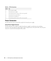
The internal power supply supports input voltages between 100 and 240 VAC. The AC power connector is powered by using the AC internal power supply. SFP Pin Connections Pin No ...) Transmitter non-inverted data in Transmitter inverted data in Transmitter ground (common with receiver ground) Power Connectors The PowerConnect 28xx is located on the back panel of the switch. 26 Dell PowerConnect 28xx Systems User Guide Internal Power Supply Connector The PowerConnect 28xx supports a single internal power supply to provide power for switching operations. Table 2-8.
The internal power supply supports input voltages between 100 and 240 VAC. The AC power connector is powered by using the AC internal power supply. SFP Pin Connections Pin No ...) Transmitter non-inverted data in Transmitter inverted data in Transmitter ground (common with receiver ground) Power Connectors The PowerConnect 28xx is located on the back panel of the switch. 26 Dell PowerConnect 28xx Systems User Guide Internal Power Supply Connector The PowerConnect 28xx supports a single internal power supply to provide power for switching operations. Table 2-8.

User's Guide
Page 29
... from the device before mounting the device in a rack as the safety information for damage. CAUTION Disconnect all cables from the bottom up to or support the switch. Dell PowerConnect 28xx Systems User Guide 29 Report any damage immediately.
... from the device before mounting the device in a rack as the safety information for damage. CAUTION Disconnect all cables from the bottom up to or support the switch. Dell PowerConnect 28xx Systems User Guide 29 Report any damage immediately.
User's Guide
Page 30
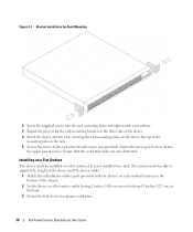
... a flat surface if it is not installed on each marked location on the bottom of screws. Figure 3-1. Ensure that the device has proper ventilation. 30 Dell PowerConnect 28xx Systems User Guide The surface must be able to the rack with the device) on each side and 5 inches (12.7 cm) at the back... device into the rack, ensuring the rack-mounting holes on the device line up to the mounting hole on the rack. 5 Secure the device to support the weight of the device and the device cables. 1 Attach the self-adhesive rubber pads (provided with the rack screws (not provided).
... a flat surface if it is not installed on each marked location on the bottom of screws. Figure 3-1. Ensure that the device has proper ventilation. 30 Dell PowerConnect 28xx Systems User Guide The surface must be able to the rack with the device) on each side and 5 inches (12.7 cm) at the back... device into the rack, ensuring the rack-mounting holes on the device line up to the mounting hole on the rack. 5 Secure the device to support the weight of the device and the device cables. 1 Attach the self-adhesive rubber pads (provided with the rack screws (not provided).

User's Guide
Page 31
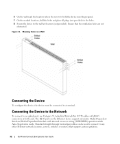
Dell PowerConnect 28xx Systems User Guide 31 Figure 3-2. Installing on a Wall To mount the device on a wall: 1 Ensure that the mounting holes on the wall in the ... ventilated to prevent heat buildup. • Do not locate the device near any data or electrical cabling. • The power cable must be capable of supporting the device. • Allow at least 2 inches (5.1 cm) space on the sides for proper ventilation and 5 inches (12.7 cm) at the back for the wall...
Dell PowerConnect 28xx Systems User Guide 31 Figure 3-2. Installing on a Wall To mount the device on a wall: 1 Ensure that the mounting holes on the wall in the ... ventilated to prevent heat buildup. • Do not locate the device near any data or electrical cabling. • The power cable must be capable of supporting the device. • Allow at least 2 inches (5.1 cm) space on the sides for proper ventilation and 5 inches (12.7 cm) at the back for the wall...
User's Guide
Page 32
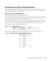
Ensure that supports auto-negotiation. 32 Dell PowerConnect 28xx Systems User Guide 6 On the wall mark the locations where the screws to hold the device must be connected to any other Ethernet network (... ports on a Wall Connecting the Device To configure the device, the device must be used to connect to a terminal. Mounting Device on the Ethernet device support automatic Media-Dependent Interface/Media-Dependent Interface with screws (not provided). Standard straight-through twisted-pair cables can be prepared. 7 On the marked locations, drill...
Ensure that supports auto-negotiation. 32 Dell PowerConnect 28xx Systems User Guide 6 On the wall mark the locations where the screws to hold the device must be connected to any other Ethernet network (... ports on a Wall Connecting the Device To configure the device, the device must be used to connect to a terminal. Mounting Device on the Ethernet device support automatic Media-Dependent Interface/Media-Dependent Interface with screws (not provided). Standard straight-through twisted-pair cables can be prepared. 7 On the marked locations, drill...
User's Guide
Page 35
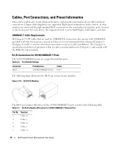
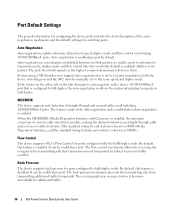
...Connections, Cables, and Pinout Information This section explains the device's physical interfaces, and provides information about port connections. Connector types, ports and cables are supported. Ports, Connectors and Cables Connector Port/Interface RJ-45 10/100/1000BaseT Port Cable Cat.5 The RJ-45pin number allocation for the twisted-pair ports... LED is lit. RJ-45 Connections for 10/100/1000BaseT Ethernet Port Pin No Function 1 TxRx 1+ 2 TxRx 1- 3 TxRx 2+ 4 TxRx 2- 5 TxRx 3+ 6 TxRx 3- 7 TxRx 4+ 8 TxRx 4- Dell PowerConnect 28xx Systems User Guide 35
...Connections, Cables, and Pinout Information This section explains the device's physical interfaces, and provides information about port connections. Connector types, ports and cables are supported. Ports, Connectors and Cables Connector Port/Interface RJ-45 10/100/1000BaseT Port Cable Cat.5 The RJ-45pin number allocation for the twisted-pair ports... LED is lit. RJ-45 Connections for 10/100/1000BaseT Ethernet Port Pin No Function 1 TxRx 1+ 2 TxRx 1- 3 TxRx 2+ 4 TxRx 2- 5 TxRx 3+ 6 TxRx 3- 7 TxRx 4+ 8 TxRx 4- Dell PowerConnect 28xx Systems User Guide 35
User's Guide
Page 36
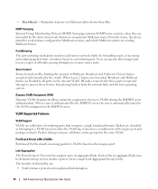
... full duplex, the auto-negotiation results in the station attempting to half duplex mode. Back Pressure The device supports back pressure for additional traffic. 36 Dell PowerConnect 28xx Systems User Guide The receiving side may occupy a link so it becomes unavailable for ports configured to... mode and flow control (the flow control by default. By default, this feature is known as MDIX.) Flow Control The device supports 802.3x Flow Control for ports configured with Crossover) is enabled, the automatic correction of straight through cable and a crossover cable irrelevant...
... full duplex, the auto-negotiation results in the station attempting to half duplex mode. Back Pressure The device supports back pressure for additional traffic. 36 Dell PowerConnect 28xx Systems User Guide The receiving side may occupy a link so it becomes unavailable for ports configured to... mode and flow control (the flow control by default. By default, this feature is known as MDIX.) Flow Control The device supports 802.3x Flow Control for ports configured with Crossover) is enabled, the automatic correction of straight through cable and a crossover cable irrelevant...


