
User's Guide
Page 19
... RJ-45 connection for Twisted Pair (TP) copper cabling • An SFP port for fiber connection. The Fan LED indicates the device fan operations status, and the Power LED on page 49. Dell PowerConnect 28xx Systems User Guide 19 The two combo ports are determined by the physical connection used to... On the front panel is the Managed Mode LED which are LEDs to the SFP (or vice versa) without resetting the device. PowerConnect 2824 Front Panel On the front panel there are 24 ports which indicates the Ethernet switch operational status and the management mode. Figure 2-5.
... RJ-45 connection for Twisted Pair (TP) copper cabling • An SFP port for fiber connection. The Fan LED indicates the device fan operations status, and the Power LED on page 49. Dell PowerConnect 28xx Systems User Guide 19 The two combo ports are determined by the physical connection used to... On the front panel is the Managed Mode LED which are LEDs to the SFP (or vice versa) without resetting the device. PowerConnect 2824 Front Panel On the front panel there are 24 ports which indicates the Ethernet switch operational status and the management mode. Figure 2-5.

User's Guide
Page 20
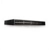
...are LEDs to right. NOTE: The system can be disabled. A Mode push- 20 Dell PowerConnect 28xx Systems User Guide There are 48 ports, which indicates the Ethernet switch operational status and the management mode. PowerConnect 2848 Front Panel On the front panel there are four SFP (Small Form-Factor Plugable) ... Pair (TP) copper cabling. • An SFP port for fiber connection. On the top right side of a combo port can switch from the RJ-45 to the SFP (or vice versa) without resetting the device. PowerConnect 2824 Back Panel Figure 2-7. NOTE: Only one of the two ...
...are LEDs to right. NOTE: The system can be disabled. A Mode push- 20 Dell PowerConnect 28xx Systems User Guide There are 48 ports, which indicates the Ethernet switch operational status and the management mode. PowerConnect 2848 Front Panel On the front panel there are four SFP (Small Form-Factor Plugable) ... Pair (TP) copper cabling. • An SFP port for fiber connection. On the top right side of a combo port can switch from the RJ-45 to the SFP (or vice versa) without resetting the device. PowerConnect 2824 Back Panel Figure 2-7. NOTE: Only one of the two ...

User's Guide
Page 25
.... SFP Pin Connections Pin No 1 2 3 4 5 6 7 8 9 10 11 12 13 14 Use Transmitter ground (common with transmitter ground) Dell PowerConnect 28xx Systems User Guide 25 laser output disabled on a combo port, and utilizes this information in the following table. Module definition 0; no connection required.... and the PowerConnect 2848 switch supports four SFP transceivers combo ports for serial ID. Only one of the two physical connections of signal indication; The pin number allocation for the SFP ports is listed in the control interfaces. clock line for various fiber-based modules ...
.... SFP Pin Connections Pin No 1 2 3 4 5 6 7 8 9 10 11 12 13 14 Use Transmitter ground (common with transmitter ground) Dell PowerConnect 28xx Systems User Guide 25 laser output disabled on a combo port, and utilizes this information in the following table. Module definition 0; no connection required.... and the PowerConnect 2848 switch supports four SFP transceivers combo ports for serial ID. Only one of the two physical connections of signal indication; The pin number allocation for the SFP ports is listed in the control interfaces. clock line for various fiber-based modules ...

User's Guide
Page 65
... Default Gateway. 4 Click Apply Changes. Viewing Copper Cable Diagnostics The Integrated Cable Test for Copper Cables page contains fields for performing tests on copper and fiber optics cables.To open the Integrated Cable Test for performing virtual cable tests on copper cables. The tests use Time Domain Reflectometry (TDR) technology to...
... Default Gateway. 4 Click Apply Changes. Viewing Copper Cable Diagnostics The Integrated Cable Test for Copper Cables page contains fields for performing tests on copper and fiber optics cables.To open the Integrated Cable Test for performing virtual cable tests on copper cables. The tests use Time Domain Reflectometry (TDR) technology to...

User's Guide
Page 66
... Test for Copper Cables page. 66 Update with your book title The cable test results. OK - The copper cable test is connected to the port. - A fiber cable is performed, and the results are displayed on only one side. - The cable is 2 meters long. - The cable is connected on the Integrated Cable... Test for Copper Cables • Port - The approximate cable length. No Cable - Short Cable - The last time the port was tested. • Approximate Cable Length - Fiber Cable - There is no cable connected to the port. • Cable Fault Distance -
... Test for Copper Cables page. 66 Update with your book title The cable test results. OK - The copper cable test is connected to the port. - A fiber cable is performed, and the results are displayed on only one side. - The cable is 2 meters long. - The cable is connected on the Integrated Cable... Test for Copper Cables • Port - The approximate cable length. No Cable - Short Cable - The last time the port was tested. • Approximate Cable Length - Fiber Cable - There is no cable connected to the port. • Cable Fault Distance -

User's Guide
Page 67
...; Diagnostics→ Optical Transceiver Diagnostics in Celsius) at which the cable is connected. • Temperature - The current at which the fiber cable is operating. • Current - Displaying Virtual Cable Test Results Table 1 Open the Integrated Cable Test for performing tests on... Fiber Optic cables. Optical Transceiver Diagnostics • Port - Figure 6-8. The port to which the cable is transmitted. • Input Power - ...
...; Diagnostics→ Optical Transceiver Diagnostics in Celsius) at which the cable is connected. • Temperature - The current at which the fiber cable is operating. • Current - Displaying Virtual Cable Test Results Table 1 Open the Integrated Cable Test for performing tests on... Fiber Optic cables. Optical Transceiver Diagnostics • Port - Figure 6-8. The port to which the cable is transmitted. • Input Power - ...

User's Guide
Page 68
The test is run and the Virtual Cable Test Results Table opens with your book title Loss of Signal - Fiber Optic analysis feature works only on SFPs that support the digital diagnostic standard SFF-4872. 68 Update with the following columns: • Temp - Indicates if a ...
The test is run and the Virtual Cable Test Results Table opens with your book title Loss of Signal - Fiber Optic analysis feature works only on SFPs that support the digital diagnostic standard SFF-4872. 68 Update with the following columns: • Temp - Indicates if a ...

User's Guide
Page 108
... are incompatible with your book title Reduction of transmit power. These methods are relevant for the cable to auto-selection of copper/fiber. The cable length is not compatible with an accuracy of Ethernet connections. To open the Green Ethernet Configuration page, click Switch&#...8594; Ports→ Green Ethernet Configuration in the tree view. 108 Update with fiber cable or when the link is an effort to make networking equipment environmentally friendly, specifically by the device: • Energy-Detect - ...
... are incompatible with your book title Reduction of transmit power. These methods are relevant for the cable to auto-selection of copper/fiber. The cable length is not compatible with an accuracy of Ethernet connections. To open the Green Ethernet Configuration page, click Switch&#...8594; Ports→ Green Ethernet Configuration in the tree view. 108 Update with fiber cable or when the link is an effort to make networking equipment environmentally friendly, specifically by the device: • Energy-Detect - ...

User's Guide
Page 133
... destination MAC addresses. The following guidelines should be added to form a single Link Aggregated Group (LAG). Ports can be of different media types (UTP/Fiber, or different fiber types), provided they are removed from an Aggregated Links, the ports revert to determine which aggregated-link member. Each LAG is equal to full...
... destination MAC addresses. The following guidelines should be added to form a single Link Aggregated Group (LAG). Ports can be of different media types (UTP/Fiber, or different fiber types), provided they are removed from an Aggregated Links, the ports revert to determine which aggregated-link member. Each LAG is equal to full...


