
User's Guide
Page 17
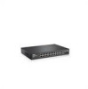
...are LEDs (Light Emitting Diode) to reset the device. For more information about management modes and transitioning between management modes and to indicate the port status. The combo 1000 Mbps optical ports can operate at 1000 Mbps, full-duplex mode. Dell PowerConnect 28xx Systems... User Guide 17 Figure 2-1. Hardware Description Switch Port Configurations PowerConnect 28xx Front and Back Panel Port Description The Dell™ PowerConnect™ 28xx switches use 10/100/1000BASE-T ports on the ...
...are LEDs (Light Emitting Diode) to reset the device. For more information about management modes and transitioning between management modes and to indicate the port status. The combo 1000 Mbps optical ports can operate at 1000 Mbps, full-duplex mode. Dell PowerConnect 28xx Systems... User Guide 17 Figure 2-1. Hardware Description Switch Port Configurations PowerConnect 28xx Front and Back Panel Port Description The Dell™ PowerConnect™ 28xx switches use 10/100/1000BASE-T ports on the ...

User's Guide
Page 27
... not overload the power circuits, wiring, and over . • Ensure that the device is not restricted. 3 Dell PowerConnect 28xx Systems User Guide 27 Opening or removing covers marked with a triangular symbol with approved equipment. • Allow ...objects into the device, as it from becoming unstable and/or falling over -current protection. Installing the PowerConnect Device This section contains information about device unpacking, location, installation, and cable connections. Do not service... shock. • Use the device only with a lighting bolt may cause electrical shock.
... not overload the power circuits, wiring, and over . • Ensure that the device is not restricted. 3 Dell PowerConnect 28xx Systems User Guide 27 Opening or removing covers marked with a triangular symbol with approved equipment. • Allow ...objects into the device, as it from becoming unstable and/or falling over -current protection. Installing the PowerConnect Device This section contains information about device unpacking, location, installation, and cable connections. Do not service... shock. • Use the device only with a lighting bolt may cause electrical shock.
User's Guide
Page 28
...There is installed within 1.5 m (5 feet) of electrical noise such as radio transmitters, broadcast amplifiers, power lines, and fluorescent lighting fixtures. • Ambient Requirements - The device is adequate frontal clearance for cabling, power connections, and ventilation. • Cabling.... Cabling is correctly installed. • Clearance - Site Requirements The PowerConnect 28xx can be mounted in a standard equipment rack, placed on a tabletop, or mounted on a secure, stable and clean surface. 4 Remove all packing material. 28 Dell PowerConnect 28xx Systems User Guide
...There is installed within 1.5 m (5 feet) of electrical noise such as radio transmitters, broadcast amplifiers, power lines, and fluorescent lighting fixtures. • Ambient Requirements - The device is adequate frontal clearance for cabling, power connections, and ventilation. • Cabling.... Cabling is correctly installed. • Clearance - Site Requirements The PowerConnect 28xx can be mounted in a standard equipment rack, placed on a tabletop, or mounted on a secure, stable and clean surface. 4 Remove all packing material. 28 Dell PowerConnect 28xx Systems User Guide
Getting Started Guide
Page 8
...surface. 4 Remove all packing material. 5 Inspect the product for installation • Documentation CD • Product Information Guide Unpacking the Device To unpack the PowerConnect device: NOTE: Before unpacking the device, inspect the packaging and report any damage immediately. 6 Installation Before installing the device, verify that water or moisture... - Allow clearance for operator access. Cabling is installed within 1.5 m (5 feet) of electrical noise such as radio transmitters, broadcast amplifiers, power lines, and fluorescent lighting fixtures. • Ambient Requirements -
...surface. 4 Remove all packing material. 5 Inspect the product for installation • Documentation CD • Product Information Guide Unpacking the Device To unpack the PowerConnect device: NOTE: Before unpacking the device, inspect the packaging and report any damage immediately. 6 Installation Before installing the device, verify that water or moisture... - Allow clearance for operator access. Cabling is installed within 1.5 m (5 feet) of electrical noise such as radio transmitters, broadcast amplifiers, power lines, and fluorescent lighting fixtures. • Ambient Requirements -

Getting Started Guide
Page 9
.... • Observe and follow the safety instructions located in your Product Information Guide. Opening or removing covers marked with a triangular symbol with a lighting bolt may cause a fire or electric shock. • Use the device only with approved equipment. • Allow the device to prevent it ...into the device, as explained in this section: • Ensure that the rack or cabinet housing the device is not exposed to the PowerConnect 2808/16/24/48 devices. These components are to be serviced by trained service technicians only. • Ensure that the power cable, extension...
.... • Observe and follow the safety instructions located in your Product Information Guide. Opening or removing covers marked with a triangular symbol with a lighting bolt may cause a fire or electric shock. • Use the device only with approved equipment. • Allow the device to prevent it ...into the device, as explained in this section: • Ensure that the rack or cabinet housing the device is not exposed to the PowerConnect 2808/16/24/48 devices. These components are to be serviced by trained service technicians only. • Ensure that the power cable, extension...

