
User's Guide
Page 3
... 1 Introduction 9 System Description 9 PowerConnect 2808 9 PowerConnect 2816 9 PowerConnect 2824 10 PowerConnect 2848 10 Summary of PowerConnect Models 11 Features 11 General Features ...Switch Port Configurations 17 PowerConnect 28xx Front and Back Panel Port Description 17 Physical Dimensions 21 LED Definitions 21 Power LED 22 Managed Mode LED 22 Fan LED (2824/2848 only 22 ...Port LEDs 22 Managed Mode Button 23 Switch Ventilation Fan 23 Cables, Port Connections, and Pinout Information 24 1000BASE-T Cable Requirements 24 RJ-45 Connections...
... 1 Introduction 9 System Description 9 PowerConnect 2808 9 PowerConnect 2816 9 PowerConnect 2824 10 PowerConnect 2848 10 Summary of PowerConnect Models 11 Features 11 General Features ...Switch Port Configurations 17 PowerConnect 28xx Front and Back Panel Port Description 17 Physical Dimensions 21 LED Definitions 21 Power LED 22 Managed Mode LED 22 Fan LED (2824/2848 only 22 ...Port LEDs 22 Managed Mode Button 23 Switch Ventilation Fan 23 Cables, Port Connections, and Pinout Information 24 1000BASE-T Cable Requirements 24 RJ-45 Connections...

User's Guide
Page 19
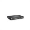
...cabling • An SFP port for fiber connection. The Fan LED indicates the device fan operations status, and the Power LED on the front panel indicates whether the device is powered on the front panel is the Managed Mode LED which offers high-speed 1000BASE-SX or 1000BASELX connection. Dell PowerConnect... 28xx Systems User Guide 19 A Mode push-button, located on the right side on or not. PowerConnect 2824 Front Panel On the front panel there are 24 ports which are LEDs to...
...cabling • An SFP port for fiber connection. The Fan LED indicates the device fan operations status, and the Power LED on the front panel indicates whether the device is powered on the front panel is the Managed Mode LED which offers high-speed 1000BASE-SX or 1000BASELX connection. Dell PowerConnect... 28xx Systems User Guide 19 A Mode push-button, located on the right side on or not. PowerConnect 2824 Front Panel On the front panel there are 24 ports which are LEDs to...

User's Guide
Page 20
... physical connection used. A Mode push- 20 Dell PowerConnect 28xx Systems User Guide PowerConnect 2824 Back Panel Figure 2-7. On each port, there are numbered 1 to 48, top down and left to indicate the port status. Port features and port controls are four SFP (Small Form-Factor Plugable) ports, designated as.... NOTE: The system can be disabled. If both RJ-45 and SFP ports are logical ports with two physical connections: • An RJ-45 connection for Twisted Pair (TP) copper cabling. • An SFP port for fiber connection. The Fan LED indicates the device fan operations ...
... physical connection used. A Mode push- 20 Dell PowerConnect 28xx Systems User Guide PowerConnect 2824 Back Panel Figure 2-7. On each port, there are numbered 1 to 48, top down and left to indicate the port status. Port features and port controls are four SFP (Small Form-Factor Plugable) ports, designated as.... NOTE: The system can be disabled. If both RJ-45 and SFP ports are logical ports with two physical connections: • An RJ-45 connection for Twisted Pair (TP) copper cabling. • An SFP port for fiber connection. The Fan LED indicates the device fan operations ...
User's Guide
Page 68
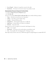
...; LOS - The transceiver has achieved power up and data is ready. The test is run and the Virtual Cable Test Results Table opens with your book title Transmitter fault. Internally measured transceiver temperature. • Voltage - Measured RX received power in...- Loss of Signal - The transceiver has archived power up and data is ready. • N/A - Error. Fiber Optic analysis feature works only on SFPs that support the digital diagnostic standard SFF-4872. 68 Update with the following columns: • Temp - Indicates if a signal loss occurred in milliwatts. ...
...; LOS - The transceiver has achieved power up and data is ready. The test is run and the Virtual Cable Test Results Table opens with your book title Transmitter fault. Internally measured transceiver temperature. • Voltage - Measured RX received power in...- Loss of Signal - The transceiver has archived power up and data is ready. • N/A - Error. Fiber Optic analysis feature works only on SFPs that support the digital diagnostic standard SFF-4872. 68 Update with the following columns: • Temp - Indicates if a signal loss occurred in milliwatts. ...

