
User's Guide
Page 3
...PowerConnect 2808 9 PowerConnect 2816 9 PowerConnect 2824 10 PowerConnect 2848 10 Summary of PowerConnect Models 11 Features 11 General Features 11 MAC Address Supported Features 13 Layer 2 Features 13 VLAN Supported Features 14 Spanning Tree Protocol Features 15 Class of Service (CoS) Features 16 Ethernet Switch Management Features 16 2 Hardware Description 17 Switch Port Configurations 17 PowerConnect... 28xx Front and Back Panel Port Description 17 Physical...
...PowerConnect 2808 9 PowerConnect 2816 9 PowerConnect 2824 10 PowerConnect 2848 10 Summary of PowerConnect Models 11 Features 11 General Features 11 MAC Address Supported Features 13 Layer 2 Features 13 VLAN Supported Features 14 Spanning Tree Protocol Features 15 Class of Service (CoS) Features 16 Ethernet Switch Management Features 16 2 Hardware Description 17 Switch Port Configurations 17 PowerConnect... 28xx Front and Back Panel Port Description 17 Physical...
User's Guide
Page 4
Power Connectors 26 Internal Power Supply Connector 26 3 Installing the PowerConnect Device 27 Installation Precautions 27 Site Requirements 28 Unpacking 28 Package Contents 28 Unpacking the Device 28 Mounting the Device 29 Overview 29 Device ...to the Device 33 Connecting a Device to a Power Supply 34 Port Connections, Cables, and Pinout Information 35 RJ-45 Connections for 10/100/1000BaseT Ports 35 Port Default Settings 36 Auto-Negotiation 36 MDI/MDIX 36 Flow Control 36 Back Pressure 36 Switching Port Default Settings 37 4 Starting and Configuring the Device 39 Booting ...
Power Connectors 26 Internal Power Supply Connector 26 3 Installing the PowerConnect Device 27 Installation Precautions 27 Site Requirements 28 Unpacking 28 Package Contents 28 Unpacking the Device 28 Mounting the Device 29 Overview 29 Device ...to the Device 33 Connecting a Device to a Power Supply 34 Port Connections, Cables, and Pinout Information 35 RJ-45 Connections for 10/100/1000BaseT Ports 35 Port Default Settings 36 Auto-Negotiation 36 MDI/MDIX 36 Flow Control 36 Back Pressure 36 Switching Port Default Settings 37 4 Starting and Configuring the Device 39 Booting ...
User's Guide
Page 6
... 93 Configuring General Device Parameters 93 7 Configuring Device Switching 95 Configuring Network Security 95 Configuring Port Based Authentication 96 Configuring Advanced Port Based Authentication 100 Authenticating Users 102 Configuring Ports 103 Defining Port Parameters 103 Aggregating Ports 105 Configuring Green Ethernet 108 Enabling Storm Control 110 Defining Port Mirroring Sessions 112 Configuring Address Tables 114 Viewing Dynamic...
... 93 Configuring General Device Parameters 93 7 Configuring Device Switching 95 Configuring Network Security 95 Configuring Port Based Authentication 96 Configuring Advanced Port Based Authentication 100 Authenticating Users 102 Configuring Ports 103 Defining Port Parameters 103 Aggregating Ports 105 Configuring Green Ethernet 108 Enabling Storm Control 110 Defining Port Mirroring Sessions 112 Configuring Address Tables 114 Viewing Dynamic...

User's Guide
Page 9
... features are managed by Dell's OpenManage Switch Administrator. PowerConnect 2808 Front Panel 1 The PowerConnect 2808 supports the following ports: • 8 Gigabit Ethernet copper ports PowerConnect 2816 The following figure illustrates the PowerConnect 2808 front panel. Introduction This User's Guide contains the information needed for the Small Office/Home Office (SOHO) that requires high performance network connectivity along with ...
... features are managed by Dell's OpenManage Switch Administrator. PowerConnect 2808 Front Panel 1 The PowerConnect 2808 supports the following ports: • 8 Gigabit Ethernet copper ports PowerConnect 2816 The following figure illustrates the PowerConnect 2808 front panel. Introduction This User's Guide contains the information needed for the Small Office/Home Office (SOHO) that requires high performance network connectivity along with ...

User's Guide
Page 11
PowerConnect Models Model PowerConnect 2808 PowerConnect 2816 PowerConnect 2824 PowerConnect 2848 Copper Ports/ RJ-45 Connectors Optical Ports/ GbE 8 built-in 10/100/1000 Base-T ports none 16 built-in 10/100/1000 Base-T ports none 24 built-in 10/100/1000 Base-T ports 2 SFP (combo) 48...forwarded before packets at all ports is disabled on a per-port basis. Provides switch management through the web interface. • Unmanaged Mode - The default status on page 49. Table 1-1. Fans baud rate is unavailable for configuration. Dell PowerConnect 28xx Systems User Guide 11...
PowerConnect Models Model PowerConnect 2808 PowerConnect 2816 PowerConnect 2824 PowerConnect 2848 Copper Ports/ RJ-45 Connectors Optical Ports/ GbE 8 built-in 10/100/1000 Base-T ports none 16 built-in 10/100/1000 Base-T ports none 24 built-in 10/100/1000 Base-T ports 2 SFP (combo) 48...forwarded before packets at all ports is disabled on a per-port basis. Provides switch management through the web interface. • Unmanaged Mode - The default status on page 49. Table 1-1. Fans baud rate is unavailable for configuration. Dell PowerConnect 28xx Systems User Guide 11...
User's Guide
Page 12
... • Cable Length • Fault-Distance 12 Dell PowerConnect 28xx Systems User Guide Port advertisement allows the system administrator to an RJ-45 port is enabled by transporting the same data using less frames. AutoMDI/MDIX Support The switch automatically detects whether the cable connected to configure the port speeds advertised. Virtual Cable Testing (VCT) VCT...
... • Cable Length • Fault-Distance 12 Dell PowerConnect 28xx Systems User Guide Port advertisement allows the system administrator to an RJ-45 port is enabled by transporting the same data using less frames. AutoMDI/MDIX Support The switch automatically detects whether the cable connected to configure the port speeds advertised. Virtual Cable Testing (VCT) VCT...

User's Guide
Page 13
... learning them from the incoming frames source address. 802.1D Bridging in Unmanaged Mode In Unmanaged Mode, the switch performs classic bridging. Dell PowerConnect 28xx Systems User Guide 13 Automatic Aging for untagged frames. However, a similar functionality may be configured for MAC...Supported Features MAC Address Capacity Support The PowerConnect 2808, 2816, 2824 switches support a total of 8K MAC addresses, and the PowerConnect 2848 supports a total of the layer 2 multicast domain even though there is an effort to the relevant ports. Addresses are transmitted to make networking ...
... learning them from the incoming frames source address. 802.1D Bridging in Unmanaged Mode In Unmanaged Mode, the switch performs classic bridging. Dell PowerConnect 28xx Systems User Guide 13 Automatic Aging for untagged frames. However, a similar functionality may be configured for MAC...Supported Features MAC Address Capacity Support The PowerConnect 2808, 2816, 2824 switches support a total of 8K MAC addresses, and the PowerConnect 2848 supports a total of the layer 2 multicast domain even though there is an effort to the relevant ports. Addresses are transmitted to make networking ...
User's Guide
Page 14
... links and the host operating system. When Layer 2 frames are forwarded, Broadcast and Multicast frames are forwarded by the switch. Link Aggregation The PowerConnect 28xx switches support up to four member ports to process these ports accept and attempt to form a single Link Aggregated Group (LAG). From the frame, the device identifies work stations to... shorter than 40m. When a user is automatically joined to an upstream Multicast router. The benefits of incoming and outgoing packets from physical link disruption 14 Dell PowerConnect 28xx Systems User Guide
... links and the host operating system. When Layer 2 frames are forwarded, Broadcast and Multicast frames are forwarded by the switch. Link Aggregation The PowerConnect 28xx switches support up to four member ports to process these ports accept and attempt to form a single Link Aggregated Group (LAG). From the frame, the device identifies work stations to... shorter than 40m. When a user is automatically joined to an upstream Multicast router. The benefits of incoming and outgoing packets from physical link disruption 14 Dell PowerConnect 28xx Systems User Guide

User's Guide
Page 15
..., and can then configure these values to the TFTP client and try to all ports on the default VLAN, until a BootP server replies. IEEE 802.1w Rapid Spanning Tree Spanning Tree can take 30-60 seconds for the switch Dell PowerConnect 28xx Systems User Guide 15 The Dynamic Host Configuration Protocol (DHCP) automates the...
..., and can then configure these values to the TFTP client and try to all ports on the default VLAN, until a BootP server replies. IEEE 802.1w Rapid Spanning Tree Spanning Tree can take 30-60 seconds for the switch Dell PowerConnect 28xx Systems User Guide 15 The Dynamic Host Configuration Protocol (DHCP) automates the...

User's Guide
Page 16
...and to be captured across the entire network. The system provides a means to collect the statistics defined in the system. 16 Dell PowerConnect 28xx Systems User Guide After a packet has been classified, it is based on the use of the queues. The system ... related to the same Class of service. The switches support four queues per port. TFTP Trivial File Transfer Protocol The PowerConnect 28xx switches support software boot image and software download through which provides network traffic statistics. The PowerConnect 28xx system can classify according to the Simple Network...
...and to be captured across the entire network. The system provides a means to collect the statistics defined in the system. 16 Dell PowerConnect 28xx Systems User Guide After a packet has been classified, it is based on the use of the queues. The system ... related to the same Class of service. The switches support four queues per port. TFTP Trivial File Transfer Protocol The PowerConnect 28xx switches support software boot image and software download through which provides network traffic statistics. The PowerConnect 28xx system can classify according to the Simple Network...

User's Guide
Page 17
.... Figure 2-1. PowerConnect 2808 Front Panel 2 On the front panel there are eight ports which indicates the Ethernet switch operational status and the management mode. On each port there are numbered 1 to 8, top down and left to indicate the port status. For more information about management modes and transitioning between management modes and to a network. Dell PowerConnect 28xx Systems...
.... Figure 2-1. PowerConnect 2808 Front Panel 2 On the front panel there are eight ports which indicates the Ethernet switch operational status and the management mode. On each port there are numbered 1 to 8, top down and left to indicate the port status. For more information about management modes and transitioning between management modes and to a network. Dell PowerConnect 28xx Systems...

User's Guide
Page 18
... 18 Dell PowerConnect 28xx Systems User Guide On the left to right. For more information about management modes and transitioning between management modes and to indicate the port status. The Power LED on the front panel indicates whether the device is the Managed Mode LED which are 16 ports which indicates the Ethernet switch operational...
... 18 Dell PowerConnect 28xx Systems User Guide On the left to right. For more information about management modes and transitioning between management modes and to indicate the port status. The Power LED on the front panel indicates whether the device is the Managed Mode LED which are 16 ports which indicates the Ethernet switch operational...

User's Guide
Page 19
...to reset the device. Dell PowerConnect 28xx Systems User Guide 19 A Mode push-button, located on the right side on a combo port, and utilizes the information in all the control interfaces. The two combo ports are two SFP (Small Form-Factor Plugable) ports, designated as ports 23 and 24, ... are 24 ports which indicates the Ethernet switch operational status and the management mode. Port features and port controls are present, the SFP port will be the active port, whereas the RJ-45 port will be used at any one of the two physical connections of a combo port can switch from the...
...to reset the device. Dell PowerConnect 28xx Systems User Guide 19 A Mode push-button, located on the right side on a combo port, and utilizes the information in all the control interfaces. The two combo ports are two SFP (Small Form-Factor Plugable) ports, designated as ports 23 and 24, ... are 24 ports which indicates the Ethernet switch operational status and the management mode. Port features and port controls are present, the SFP port will be the active port, whereas the RJ-45 port will be used at any one of the two physical connections of a combo port can switch from the...

User's Guide
Page 20
... LED on the front panel indicates whether the device is the Managed Mode LED which indicates the Ethernet switch operational status and the management mode. Port features and port controls are 48 ports, which offers high-speed 1000BASE-SX or 1000BASE-LX connection. The system automatically detects the media used ...On the front panel there are determined by the physical connection used on or not. A Mode push- 20 Dell PowerConnect 28xx Systems User Guide Figure 2-6. If both RJ-45 and SFP ports are numbered 1 to 48, top down and left to the SFP (or vice versa) without resetting the ...
... LED on the front panel indicates whether the device is the Managed Mode LED which indicates the Ethernet switch operational status and the management mode. Port features and port controls are 48 ports, which offers high-speed 1000BASE-SX or 1000BASE-LX connection. The system automatically detects the media used ...On the front panel there are determined by the physical connection used on or not. A Mode push- 20 Dell PowerConnect 28xx Systems User Guide Figure 2-6. If both RJ-45 and SFP ports are numbered 1 to 48, top down and left to the SFP (or vice versa) without resetting the ...

User's Guide
Page 22
...Port LEDs 10/100/1000BASE-T Port LEDs Each 10/100/1000BASE-T port has two LEDs. Diagnostics has failed. One or more information about management modes and transitioning between them, see "Management Modes" on the right LED. The following table describes the Power Supply status LED indications. Indicates the switch...valid image. Fan LED (2824/2848 only) On the PowerConnect 2824 and PowerConnect 2848 front panel there is a Power LED. The following figure illustrates the RJ-45 10/100/1000BASE-T LEDs. 22 Dell PowerConnect 28xx Systems User Guide Fan LED Indications LED Color Green ...
...Port LEDs 10/100/1000BASE-T Port LEDs Each 10/100/1000BASE-T port has two LEDs. Diagnostics has failed. One or more information about management modes and transitioning between them, see "Management Modes" on the right LED. The following table describes the Power Supply status LED indications. Indicates the switch...valid image. Fan LED (2824/2848 only) On the PowerConnect 2824 and PowerConnect 2848 front panel there is a Power LED. The following figure illustrates the RJ-45 10/100/1000BASE-T LEDs. 22 Dell PowerConnect 28xx Systems User Guide Fan LED Indications LED Color Green ...

User's Guide
Page 23
.... Switch Ventilation Fan The PowerConnect 2848 switch has three fans and the PowerConnect 2824 switch has one fan for at 1000 Mbps. The port is for resetting the device. To transition between Managed Mode and Unmanaged (or Secure) Mode and for changing between modes, press the button normally. The PowerConnect 2808 and PowerConnect 2816 devices have no internal fans. Dell PowerConnect...
.... Switch Ventilation Fan The PowerConnect 2848 switch has three fans and the PowerConnect 2824 switch has one fan for at 1000 Mbps. The port is for resetting the device. To transition between Managed Mode and Unmanaged (or Secure) Mode and for changing between modes, press the button normally. The PowerConnect 2808 and PowerConnect 2816 devices have no internal fans. Dell PowerConnect...
User's Guide
Page 24
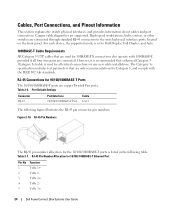
...connected. However, it is recommended that enhanced Category 5 (Category 5e)cable is used for the 10/100/1000BASE-T ports is set to the switch physical interface ports, located on the front panel. RJ-45 Pin Number Allocation for Category 5, and comply with 1000BASE-T, provided if all... includes test parameters that are used for 10/100/1000BASE-T Ports The 10/100/1000BASE-T ports are only recommendations for 10/100/ 1000BASE-T Ethernet Port Pin No 1 2 3 4 5 Function TxRx 1+ TxRx 1TxRx 2+ TxRx 2TxRx 3+ 24 Dell PowerConnect 28xx Systems User Guide RJ-45 Pin Numbers The RJ-45...
...connected. However, it is recommended that enhanced Category 5 (Category 5e)cable is used for the 10/100/1000BASE-T ports is set to the switch physical interface ports, located on the front panel. RJ-45 Pin Number Allocation for Category 5, and comply with 1000BASE-T, provided if all... includes test parameters that are used for 10/100/1000BASE-T Ports The 10/100/1000BASE-T ports are only recommendations for 10/100/ 1000BASE-T Ethernet Port Pin No 1 2 3 4 5 Function TxRx 1+ TxRx 1TxRx 2+ TxRx 2TxRx 3+ 24 Dell PowerConnect 28xx Systems User Guide RJ-45 Pin Numbers The RJ-45...

User's Guide
Page 25
...to the system administrator. laser output disabled on a combo port, and utilizes this information in the following table. AC coupled. SFP Ports The PowerConnect 2824 switch supports two SFP transceivers combo ports, and the PowerConnect 2848 switch supports four SFP transceivers combo ports for 10/100/ 1000BASE-T Ethernet Port Pin No 6 7 8 Function TxRx 3TxRx 4+ TxRx ...ground (common with transmitter ground) Receiver ground (common with receiver ground) Transmitter fault Transmitter disable; Receiver ground (common with transmitter ground) Dell PowerConnect 28xx Systems User Guide 25
...to the system administrator. laser output disabled on a combo port, and utilizes this information in the following table. AC coupled. SFP Ports The PowerConnect 2824 switch supports two SFP transceivers combo ports, and the PowerConnect 2848 switch supports four SFP transceivers combo ports for 10/100/ 1000BASE-T Ethernet Port Pin No 6 7 8 Function TxRx 3TxRx 4+ TxRx ...ground (common with transmitter ground) Receiver ground (common with receiver ground) Transmitter fault Transmitter disable; Receiver ground (common with transmitter ground) Dell PowerConnect 28xx Systems User Guide 25
User's Guide
Page 32
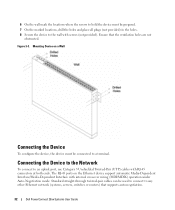
...automatic Media-Dependent Interface/Media-Dependent Interface with internal crossover wiring (MDI/MDIX) operation under Auto-Negotiation mode. The RJ-45 ports on a Wall Connecting the Device To configure the device, the device must be prepared. 7 On the marked locations, drill..., servers, switches or routers) that the ventilation holes are not obstructed. Connecting the Device to the Network To connect to an uplink port, use Category 5 Unshielded Twisted-Pair (UTP) cables with screws (not provided). Ensure that supports auto-negotiation. 32 Dell PowerConnect 28xx Systems User...
...automatic Media-Dependent Interface/Media-Dependent Interface with internal crossover wiring (MDI/MDIX) operation under Auto-Negotiation mode. The RJ-45 ports on a Wall Connecting the Device To configure the device, the device must be prepared. 7 On the marked locations, drill..., servers, switches or routers) that the ventilation holes are not obstructed. Connecting the Device to the Network To connect to an uplink port, use Category 5 Unshielded Twisted-Pair (UTP) cables with screws (not provided). Ensure that supports auto-negotiation. 32 Dell PowerConnect 28xx Systems User...
User's Guide
Page 130
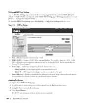
... VLAN ID (PVID) is updated. 130 Update with your book title VLAN Port Settings • Port - Only tagged packets are accepted on the port. Enables or disables Ingress filtering on the port. - To open the VLAN Port Settings page, click Switch→ VLAN→ Port Settings in the VLAN. • PVID (1-4095)- Assigns a VLA N ID to untagged...
... VLAN ID (PVID) is updated. 130 Update with your book title VLAN Port Settings • Port - Only tagged packets are accepted on the port. Enables or disables Ingress filtering on the port. - To open the VLAN Port Settings page, click Switch→ VLAN→ Port Settings in the VLAN. • PVID (1-4095)- Assigns a VLA N ID to untagged...


