
User's Guide
Page 3
...SFP Combo ports 8 48 1-Gigabit Ethernet Ports 8 Features 9 General Features 9 MAC Address Supported Features 11 Layer 2 Features 11 VLAN Supported Features 12 Class of Service (CoS) Features 12 Ethernet Switch Management Features 13 Port Default Settings 13 2 Hardware Description Switch Port Configurations 15 PowerConnect 2708/2716/2724/2748... Front Panel Port Description . . . . 15 Physical Dimensions 19 LED Definitions 19 Power LED 19 Managed Mode LED 19 Fan LED (2748 only 20 Port LEDs 20 ...
...SFP Combo ports 8 48 1-Gigabit Ethernet Ports 8 Features 9 General Features 9 MAC Address Supported Features 11 Layer 2 Features 11 VLAN Supported Features 12 Class of Service (CoS) Features 12 Ethernet Switch Management Features 13 Port Default Settings 13 2 Hardware Description Switch Port Configurations 15 PowerConnect 2708/2716/2724/2748... Front Panel Port Description . . . . 15 Physical Dimensions 19 LED Definitions 19 Power LED 19 Managed Mode LED 19 Fan LED (2748 only 20 Port LEDs 20 ...
User's Guide
Page 8
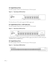
... switch supports 16 GbE copper ports. 24 1-Gigabit Ethernet Ports + 2 SFP Combo ports The following figure illustrates the PowerConnect 2748 front panel. Figure 1-3. PowerConnect 2724 Front Panel The PowerConnect 2724 switch supports 24 GbE copper ports and has two SFP combo ports (1000BASE-SX or 1000BASE-LX). 48 1-Gigabit Ethernet Ports The following figure illustrates the...
... switch supports 16 GbE copper ports. 24 1-Gigabit Ethernet Ports + 2 SFP Combo ports The following figure illustrates the PowerConnect 2748 front panel. Figure 1-3. PowerConnect 2724 Front Panel The PowerConnect 2724 switch supports 24 GbE copper ports and has two SFP combo ports (1000BASE-SX or 1000BASE-LX). 48 1-Gigabit Ethernet Ports The following figure illustrates the...

User's Guide
Page 17
...the front panel is powered on the front panel, restores the device's default settings configuration. On the left to the SFP (or vice versa) without resetting the device. PowerConnect 2724 Front Panel On the front panel there are 24 ports which are logical ports with two physical connections: •... An RJ-45 connection for Twisted Pair (TP) copper cabling • An SFP port for fiber connection. Port features and port controls are LEDs to indicate the port status. NOTE: The system can be disabled. PowerConnect 2724 Back Panel 17 The two combo ports are numbered 1 to 24, top...
...the front panel is powered on the front panel, restores the device's default settings configuration. On the left to the SFP (or vice versa) without resetting the device. PowerConnect 2724 Front Panel On the front panel there are 24 ports which are logical ports with two physical connections: •... An RJ-45 connection for Twisted Pair (TP) copper cabling • An SFP port for fiber connection. Port features and port controls are LEDs to indicate the port status. NOTE: The system can be disabled. PowerConnect 2724 Back Panel 17 The two combo ports are numbered 1 to 24, top...

User's Guide
Page 18
... the Ethernet switch operational status. On the top right side of the PowerConnect 2748 device. Figure 2-8. NOTE: Only one time. If both RJ-45 and SFP ports are LEDs to the SFP (or vice versa) without resetting the device. PowerConnect 2748 Back Panel 18 NOTE: The system can be disabled. On each port..., there are present, the SFP port will be the active port, whereas the RJ-45...
... the Ethernet switch operational status. On the top right side of the PowerConnect 2748 device. Figure 2-8. NOTE: Only one time. If both RJ-45 and SFP ports are LEDs to the SFP (or vice versa) without resetting the device. PowerConnect 2748 Back Panel 18 NOTE: The system can be disabled. On each port..., there are present, the SFP port will be the active port, whereas the RJ-45...

User's Guide
Page 21
... is transmitting or receiving data at either 10 or 100 Mbps. The Managed Mode button is occurring. SFP Port LED The following table describes the SFP LED indications. Managed Mode Button The PowerConnect 2708/2716/2724/2748 has a Managed Mode push button on the front panel. Table 2-5. Green Flashing Activity is for changing between...
... is transmitting or receiving data at either 10 or 100 Mbps. The Managed Mode button is occurring. SFP Port LED The following table describes the SFP LED indications. Managed Mode Button The PowerConnect 2708/2716/2724/2748 has a Managed Mode push button on the front panel. Table 2-5. Green Flashing Activity is for changing between...
User's Guide
Page 23
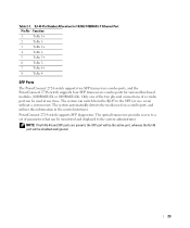
...be used on a combo port, and utilizes this information in the control interfaces. PowerConnect 2724 switch supports SFP diagnostics. NOTE: If both RJ-45 and SFP ports are present, the SFP port will be the active port, whereas the RJ-45 port will be monitored...the media used at any time. The optical transceiver provides access to the SFP (or vice versa) without a system reset. SFP Ports The PowerConnect 2724 switch supports two SFP transceivers combo ports, and the PowerConnect 2748 switch supports four SFP transceivers combo ports for 10/100/ 1000BASE-T Ethernet Port Pin No Function 1...
...be used on a combo port, and utilizes this information in the control interfaces. PowerConnect 2724 switch supports SFP diagnostics. NOTE: If both RJ-45 and SFP ports are present, the SFP port will be the active port, whereas the RJ-45 port will be monitored...the media used at any time. The optical transceiver provides access to the SFP (or vice versa) without a system reset. SFP Ports The PowerConnect 2724 switch supports two SFP transceivers combo ports, and the PowerConnect 2748 switch supports four SFP transceivers combo ports for 10/100/ 1000BASE-T Ethernet Port Pin No Function 1...
User's Guide
Page 24
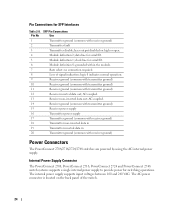
SFP Pin Connections Pin No Use 1 Transmitter ground (common with receiver ground) Power Connectors The PowerConnect 2708/2716/2724/2748 switches are powered by using the AC internal power supply. data line for serial ID. 6 Module definition...with transmitter ground) 12 Receiver inverted data out; Internal Power Supply Connector The PowerConnect 2708, PowerConnect 2716, PowerConnect 2724 and PowerConnect 2748 switch systems supports a single internal power supply to provide power for SFP Interfaces Table 2-8. The internal power supply supports input voltages between 100 and 240...
SFP Pin Connections Pin No Use 1 Transmitter ground (common with receiver ground) Power Connectors The PowerConnect 2708/2716/2724/2748 switches are powered by using the AC internal power supply. data line for serial ID. 6 Module definition...with transmitter ground) 12 Receiver inverted data out; Internal Power Supply Connector The PowerConnect 2708, PowerConnect 2716, PowerConnect 2724 and PowerConnect 2748 switch systems supports a single internal power supply to provide power for SFP Interfaces Table 2-8. The internal power supply supports input voltages between 100 and 240...
User's Guide
Page 63
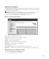
... (LOS) occurred in the tree view. Displaying Optical Transceivers Diagnostics Test Results 1 Open the Optical Transceiver Diagnostics page. 2 Select an optic cable interface to PowerConnect 2724 device's SFP ports, which the cable is ready. Figure 6-14. Temperature - Input Power - Indicates if a loss of Signal - The port on Fiber Optic cables. Measured TX...
... (LOS) occurred in the tree view. Displaying Optical Transceivers Diagnostics Test Results 1 Open the Optical Transceiver Diagnostics page. 2 Select an optic cable interface to PowerConnect 2724 device's SFP ports, which the cable is ready. Figure 6-14. Temperature - Input Power - Indicates if a loss of Signal - The port on Fiber Optic cables. Measured TX...

