User's Guide
Page 9
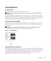
.../MDIX and therefore automatically detect the type of the switch. Using multiple cables to connect the network device. All ports on the switch automatically negotiate speed and whether to the switch. Connecting Devices RJ-45 Switch Ports RJ-45 connectors are located on the front ...networking cables can be used for connecting devices at 1000-Mbps Gigabit Ethernet speed. These switching ports allow users to connect the switches to Each Other Each port supports Auto MDI and MDIX functionality. Connecting Switches to 10Base-T and 100Base-T devices on ports 1-16 (2216), ports 1-24 (2224, 2324...
.../MDIX and therefore automatically detect the type of the switch. Using multiple cables to connect the network device. All ports on the switch automatically negotiate speed and whether to the switch. Connecting Devices RJ-45 Switch Ports RJ-45 connectors are located on the front ...networking cables can be used for connecting devices at 1000-Mbps Gigabit Ethernet speed. These switching ports allow users to connect the switches to Each Other Each port supports Auto MDI and MDIX functionality. Connecting Switches to 10Base-T and 100Base-T devices on ports 1-16 (2216), ports 1-24 (2224, 2324...
User's Guide
Page 10
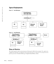
... levels of IEEE 802.1p priority are mapped to the two priority queues of -Service The switch supports tag-based prioritization following a Weighted Round Robin scheme. 10 Introduction Large Workgroup PowerConnect 1000Base-T 2324 10/100Base-T PC Network Printer PowerConnect 1000Base-T 2324 Server 10/100Base-T PC Firewall Router Class-of each port, the two priority queues are...
... levels of IEEE 802.1p priority are mapped to the two priority queues of -Service The switch supports tag-based prioritization following a Weighted Round Robin scheme. 10 Introduction Large Workgroup PowerConnect 1000Base-T 2324 10/100Base-T PC Network Printer PowerConnect 1000Base-T 2324 Server 10/100Base-T PC Firewall Router Class-of each port, the two priority queues are...

User's Guide
Page 13
... the wall. 6 Insert and tighten the screws through each side of the mounting brackets. Technical Information Table 1-2. • Do not locate the switch where there may be data or electrical cabling located directly behind the unit. • The power cable must reach an outlet. 2 Use the ...supplied screws to attach a mounting bracket to each of the switch (see Figure 1-8). Specifications Network Protocol and Standards Compatibility IEEE 802.3 CSMA/CD IEEE 802.3 10Base-T IEEE 802.3u 100Base-TX IEEE 802.3z/ab 1000Base-T IEEE ...
... the wall. 6 Insert and tighten the screws through each side of the mounting brackets. Technical Information Table 1-2. • Do not locate the switch where there may be data or electrical cabling located directly behind the unit. • The power cable must reach an outlet. 2 Use the ...supplied screws to attach a mounting bracket to each of the switch (see Figure 1-8). Specifications Network Protocol and Standards Compatibility IEEE 802.3 CSMA/CD IEEE 802.3 10Base-T IEEE 802.3u 100Base-TX IEEE 802.3z/ab 1000Base-T IEEE ...
User's Guide
Page 17
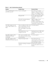
... lower Incorrect cable grade. Damaged cable. The LED blinks only when traffic is being passed to capacity. Link LED is reaching its maximum Resegment the network to or sent from a device that the port or NIC on the attached device is lighted, but the activity (ACT) LED does not blink. .... Some collisions take place during normal operation. Ensure that any cables that you are set to the switch and use a shorter cable. Table 2-1. This can be damaged. Test any devices connected to the switch are using Category 5 cable or better for all 10Base-T and 100Base-T links, or Category 5e for...
... lower Incorrect cable grade. Damaged cable. The LED blinks only when traffic is being passed to capacity. Link LED is reaching its maximum Resegment the network to or sent from a device that the port or NIC on the attached device is lighted, but the activity (ACT) LED does not blink. .... Some collisions take place during normal operation. Ensure that any cables that you are set to the switch and use a shorter cable. Table 2-1. This can be damaged. Test any devices connected to the switch are using Category 5 cable or better for all 10Base-T and 100Base-T links, or Category 5e for...


