Service Manual
Page 3
... 1-7 Desktop Chassis 1-7 Thermal Monitoring 1-7 System Unit 1-8 System Power Supply 1-8 Pin Assignments for the DC Power Connectors 1-8 DC Power Distribution 1-10 System Board Layout 1-12 Video Memory 1-12 Main Memory 1-13 System Board Jumpers 1-13 Interrupt Assignments 1-14 DMA Channel Assignments 1-15 Technical Specifications 1-16 v
... 1-7 Desktop Chassis 1-7 Thermal Monitoring 1-7 System Unit 1-8 System Power Supply 1-8 Pin Assignments for the DC Power Connectors 1-8 DC Power Distribution 1-10 System Board Layout 1-12 Video Memory 1-12 Main Memory 1-13 System Board Jumpers 1-13 Interrupt Assignments 1-14 DMA Channel Assignments 1-15 Technical Specifications 1-16 v
Service Manual
Page 10
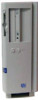
System Features In addition to the standard features found in a traditional personal computer, the Dell OptiPlex GXpro desktop systems include the following the text in this chapter. When following new and/or advanced features: • Dual-processor capability. • Advanced combination ISA ... when used with two USB-compliant connectors (included on systems containing the 10/100-Mbps NIC). • Desktop chassis. • Thermal monitoring. • Main system memory consisting of 16 to the system unit is as shown in Figure 1-1. 1-2 Dell OptiPlex GXpro Systems Service Manual
System Features In addition to the standard features found in a traditional personal computer, the Dell OptiPlex GXpro desktop systems include the following the text in this chapter. When following new and/or advanced features: • Dual-processor capability. • Advanced combination ISA ... when used with two USB-compliant connectors (included on systems containing the 10/100-Mbps NIC). • Desktop chassis. • Thermal monitoring. • Main system memory consisting of 16 to the system unit is as shown in Figure 1-1. 1-2 Dell OptiPlex GXpro Systems Service Manual
Service Manual
Page 13
...), Plug and Play ISA expansion cards, and PCI expansion cards. The ISA Configuration Utility (ICU) included with the ICU, the system automatically assigns any required memory space, IRQ lines, and DMA channels to take advantage of two processors, dual-processing systems must have multiprocessing operating systems, such as the system board...
...), Plug and Play ISA expansion cards, and PCI expansion cards. The ISA Configuration Utility (ICU) included with the ICU, the system automatically assigns any required memory space, IRQ lines, and DMA channels to take advantage of two processors, dual-processing systems must have multiprocessing operating systems, such as the system board...
Service Manual
Page 19
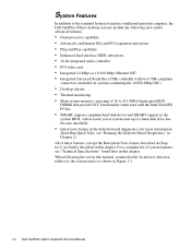
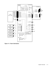
... POWER2 +12 VDC FAN optional P2 drive optional P3 drive P4 3.5-inch diskette drive P5 internal hard-disk drive P6 internal hard-disk drive main memory sockets DIMM_A DIMM_B DIMM_C DIMM_D MICROPROCESSOR +2.1-3.5 VDC +3.3 VDC +5 VFP +5 VDC FUSE +5 VDC FUSE +5 VDC +5 VDC processor core regulator 2ND_CPU +2.1-3.5 VDC +3.3 VDC PANEL USB KYBD MOUSE...
... POWER2 +12 VDC FAN optional P2 drive optional P3 drive P4 3.5-inch diskette drive P5 internal hard-disk drive P6 internal hard-disk drive main memory sockets DIMM_A DIMM_B DIMM_C DIMM_D MICROPROCESSOR +2.1-3.5 VDC +3.3 VDC +5 VFP +5 VDC FUSE +5 VDC FUSE +5 VDC +5 VDC processor core regulator 2ND_CPU +2.1-3.5 VDC +3.3 VDC PANEL USB KYBD MOUSE...
Service Manual
Page 20
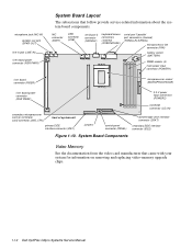
... power connector (RSR PWR1) System Board Layout The subsections that came with your system for information on removing and replacing video-memory upgrade chips. 1-12 Dell OptiPlex GXpro Systems Service Manual System Board Components Video Memory See the documentation from the video card manufacturer that follow provide service-related information about the system board components.
... power connector (RSR PWR1) System Board Layout The subsections that came with your system for information on removing and replacing video-memory upgrade chips. 1-12 Dell OptiPlex GXpro Systems Service Manual System Board Components Video Memory See the documentation from the video card manufacturer that follow provide service-related information about the system board components.
Service Manual
Page 21
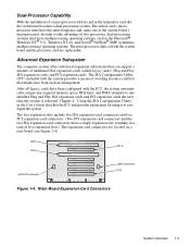
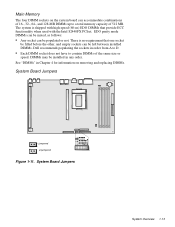
... DIMMs can be mixed, as follows: • Any socket can be left between installed DIMMs. Dell recommends populating the sockets in order from A to D. • Each DIMM socket does not have to a total memory capacity of the same size or speed. There is shipped with the Intel 82440FX PCIset. The system...-, 64-, and 128-MB DIMMs up to contain DIMMs of 512 MB. See "DIMMs" in any order. DIMMs may be populated or not. Main Memory The four DIMM sockets on removing and replacing DIMMs. System Board Jumpers jumpered unjumpered Figure 1-11. System Board Jumpers System Overview 1-13
... DIMMs can be mixed, as follows: • Any socket can be left between installed DIMMs. Dell recommends populating the sockets in order from A to D. • Each DIMM socket does not have to a total memory capacity of the same size or speed. There is shipped with the Intel 82440FX PCIset. The system...-, 64-, and 128-MB DIMMs up to contain DIMMs of 512 MB. See "DIMMs" in any order. DIMMs may be populated or not. Main Memory The four DIMM sockets on removing and replacing DIMMs. System Board Jumpers jumpered unjumpered Figure 1-11. System Board Jumpers System Overview 1-13
Service Manual
Page 25
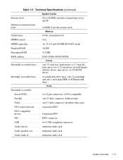
... drive; Technical Specifications (continued) System Clocks System clock 60 or 66 MHz (matches external processor speed) Diskette/communications ports 24 MHz from the system clock Memory Architecture 64-bit, noninterleaved DIMM sockets four DIMM capacities 16, 32, 64, and 128 MB, EDO ECC mode Standard RAM 16 MB Maximum RAM 512...
... drive; Technical Specifications (continued) System Clocks System clock 60 or 66 MHz (matches external processor speed) Diskette/communications ports 24 MHz from the system clock Memory Architecture 64-bit, noninterleaved DIMM sockets four DIMM capacities 16, 32, 64, and 128 MB, EDO ECC mode Standard RAM 16 MB Maximum RAM 512...
Service Manual
Page 31
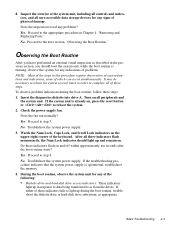
... any indications of problems. NOTE: Most of the steps in order to or from the drives. No. If the system unit is operational, troubleshoot the memory. 4. Does the inspection reveal any of the keyboard. It may be necessary to reboot the system several times in this procedure require observation of system...
... any indications of problems. NOTE: Most of the steps in order to or from the drives. No. If the system unit is operational, troubleshoot the memory. 4. Does the inspection reveal any of the keyboard. It may be necessary to reboot the system several times in this procedure require observation of system...
Service Manual
Page 33
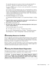
...be installed at all. Yes. Check all of the system to remove the screw that secures the card-mounting bracket. Because a device may require dedicated memory spaces, interrupt levels, or DMA channels, all cable connectors inside the system unit to verify that the same resource is assigned to two or more...to their power sources, and turn them on. Grasp the card by its connector. For information about these jumpers, see "System Board Jumpers" in Chapter 1. 5. Dell recommends that resource conflicts might exist, check the system and reassign the resources as necessary.
...be installed at all. Yes. Check all of the system to remove the screw that secures the card-mounting bracket. Because a device may require dedicated memory spaces, interrupt levels, or DMA channels, all cable connectors inside the system unit to verify that the same resource is assigned to two or more...to their power sources, and turn them on. Grasp the card by its connector. For information about these jumpers, see "System Board Jumpers" in Chapter 1. 5. Dell recommends that resource conflicts might exist, check the system and reassign the resources as necessary.
Service Manual
Page 34
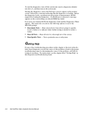
... from all tests for technical assistance. If no errors are found in the Diagnostics and Troubleshooting Guide. 2-6 Dell OptiPlex GXpro Systems Service Manual Starting the diagnostics causes the Dell logo screen to isolate a failure • Run All Tests - Tests a particular area or subsystem Getting ... choose the following options or exit to the proper troubleshooting steps for determining the source of the problem, call Dell for a thorough test of main memory (RAM) required for loading the diagnostics. Before the diagnostics loads, a program tests the portion of the system...
... from all tests for technical assistance. If no errors are found in the Diagnostics and Troubleshooting Guide. 2-6 Dell OptiPlex GXpro Systems Service Manual Starting the diagnostics causes the Dell logo screen to isolate a failure • Run All Tests - Tests a particular area or subsystem Getting ... choose the following options or exit to the proper troubleshooting steps for determining the source of the problem, call Dell for a thorough test of main memory (RAM) required for loading the diagnostics. Before the diagnostics loads, a program tests the portion of the system...
Service Manual
Page 36
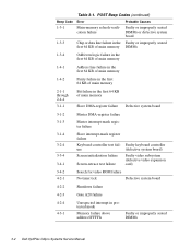
... (defective video expansion card) 3-4-2 4-2-1 Search for video ROM failure No timer tick Defective system board 4-2-2 Shutdown failure 4-2-3 Gate A20 failure 4-2-4 4-3-1 Unexpected interrupt in protected mode Memory failure above address 0FFFFh Faulty or improperly seated DIMMs 3-2 Dell OptiPlex GXpro Systems Service Manual Table 3-1. POST Beep Codes (continued) Beep Code Error Probable Causes 1-3-1 Main...
... (defective video expansion card) 3-4-2 4-2-1 Search for video ROM failure No timer tick Defective system board 4-2-2 Shutdown failure 4-2-3 Gate A20 failure 4-2-4 4-3-1 Unexpected interrupt in protected mode Memory failure above address 0FFFFh Faulty or improperly seated DIMMs 3-2 Dell OptiPlex GXpro Systems Service Manual Table 3-1. POST Beep Codes (continued) Beep Code Error Probable Causes 1-3-1 Main...
Service Manual
Page 38
...hard-disk drive. Faulty diskette, faulty or improperly connected diskette/tape drive interface cable, or loose power cable. 3-4 Dell OptiPlex GXpro Systems Service Manual Faulty diskette/tape drive subsystem or hard-disk drive subsystem (defective system board). Diskette/tape drive controller ... cable. System received unrecoverable data-read diskette. Faulty interface cable or connector. Controller has failed Data error Decreasing available memory Diskette drive 0 seek failure Diskette drive 1 seek failure Diskette read error. Bad command or file name Command entered ...
...hard-disk drive. Faulty diskette, faulty or improperly connected diskette/tape drive interface cable, or loose power cable. 3-4 Dell OptiPlex GXpro Systems Service Manual Faulty diskette/tape drive subsystem or hard-disk drive subsystem (defective system board). Diskette/tape drive controller ... cable. System received unrecoverable data-read diskette. Faulty interface cable or connector. Controller has failed Data error Decreasing available memory Diskette drive 0 seek failure Diskette drive 1 seek failure Diskette read error. Bad command or file name Command entered ...
Service Manual
Page 41
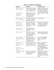
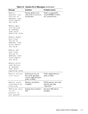
...Error Messages (continued) Message Definition Probable Causes Memory address line failure at address was incorrect. Memory data line failure at address, read value expecting value Memory double word logic failure at address, read value expecting value Memory odd/ even logic failure at address, read...failure at address, read at address, read value expecting value During memory test, value read value expecting value Memory allocation error Memory tests terminated by pressing . Memory test did not complete. POST memory test terminated by keystroke "Network card is not present in the ...
...Error Messages (continued) Message Definition Probable Causes Memory address line failure at address was incorrect. Memory data line failure at address, read value expecting value Memory double word logic failure at address, read value expecting value Memory odd/ even logic failure at address, read...failure at address, read at address, read value expecting value During memory test, value read value expecting value Memory allocation error Memory tests terminated by pressing . Memory test did not complete. POST memory test terminated by keystroke "Network card is not present in the ...
Service Manual
Page 71
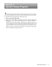
... A-1 then shut down the system and try again. Appendix A System Setup Program This appendix describes the System Setup program, which is used to load into memory, the message disappears, and you cannot enter the System Setup program. Press immediately after the monitor displays the message Press for System Setup. To enter...
... A-1 then shut down the system and try again. Appendix A System Setup Program This appendix describes the System Setup program, which is used to load into memory, the message disappears, and you cannot enter the System Setup program. Press immediately after the monitor displays the message Press for System Setup. To enter...
Service Manual
Page 72
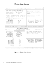
... (hours:minutes: seconds) for the internal clock/ calendar. To change values Alt-P next Esc exit Alt-B reboot Figure A-1. System Setup Screens A-2 Dell OptiPlex GXpro Systems Service Manual Microprocessor: Level 2 Cache: System Memory: Service Tag: Pentium Pro-200 512 KB Integrated 64 MB ECC EDO XXXXX Tab,Shift-Tab change fields change values Alt-P next...
... (hours:minutes: seconds) for the internal clock/ calendar. To change values Alt-P next Esc exit Alt-B reboot Figure A-1. System Setup Screens A-2 Dell OptiPlex GXpro Systems Service Manual Microprocessor: Level 2 Cache: System Memory: Service Tag: Pentium Pro-200 512 KB Integrated 64 MB ECC EDO XXXXX Tab,Shift-Tab change fields change values Alt-P next...

Service Manual
Page 73
... the parameters directly. Drives: Primary Secondary Identifies drives attached to Auto. If none of the supported drive types match the parameters of memory available as extended memory. NOTE: For EIDE devices such as the boot drive. Table A-1. System Setup Program A-3 Category options always match physical locations of ...connectors on system board. To do not use this feature, highlight the appropriate drive category and type a (for each of memory available to display User1. For EIDE hard-disk drives, the system provides an automatic drive-type detect feature. Base...
... the parameters directly. Drives: Primary Secondary Identifies drives attached to Auto. If none of the supported drive types match the parameters of memory available as extended memory. NOTE: For EIDE devices such as the boot drive. Table A-1. System Setup Program A-3 Category options always match physical locations of ...connectors on system board. To do not use this feature, highlight the appropriate drive category and type a (for each of memory available to display User1. For EIDE hard-disk drives, the system provides an automatic drive-type detect feature. Base...
Service Manual
Page 74
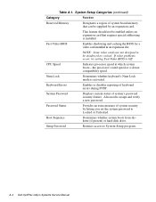
... new password. Also used to be shadowed or cached. System Password Displays current status of keyboard errors during POST. A-4 Dell OptiPlex GXpro Systems Service Manual Fast Video BIOS Enables shadowing and caching the BIOS for a video card installed in an expansion slot. Num...addressing is activated. Table A-1. Setup Password Restricts access to System Setup program. System Setup Categories (continued) Category Function Reserved Memory Designates a region of system security by an expansion card. This feature should not be supplied by letting you set the ...
... new password. Also used to be shadowed or cached. System Password Displays current status of keyboard errors during POST. A-4 Dell OptiPlex GXpro Systems Service Manual Fast Video BIOS Enables shadowing and caching the BIOS for a video card installed in an expansion slot. Num...addressing is activated. Table A-1. Setup Password Restricts access to System Setup program. System Setup Categories (continued) Category Function Reserved Memory Designates a region of system security by an expansion card. This feature should not be supplied by letting you set the ...
Service Manual
Page 76
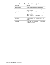
Level 2 Cache Displays size of level-2 cache memory in system, except for memory on EMS expansion cards. A-6 Dell OptiPlex GXpro Systems Service Manual System Memory Displays entire amount of microprocessor installed. If EDO DIMMs are installed, EDO is assigned. Asset Tag Displays the asset tag number up to ten characters ...
Level 2 Cache Displays size of level-2 cache memory in system, except for memory on EMS expansion cards. A-6 Dell OptiPlex GXpro Systems Service Manual System Memory Displays entire amount of microprocessor installed. If EDO DIMMs are installed, EDO is assigned. Asset Tag Displays the asset tag number up to ten characters ...
Service Manual
Page 79
L LINE-IN connector, 1-12, 4-16 line-in jack, 1-4, 1-12, 4-16 M memory, main, 1-2, 1-13 messages, error, 3-3 microphone jack, 1-4, 1-12 microprocessor release lever, 4-21 removal, 4-21 secondary, removal, 4-23 socket, 1-12, 4-16 microprocessor fan removal, 4-15 mouse connector ...
L LINE-IN connector, 1-12, 4-16 line-in jack, 1-4, 1-12, 4-16 M memory, main, 1-2, 1-13 messages, error, 3-3 microphone jack, 1-4, 1-12 microprocessor release lever, 4-21 removal, 4-21 secondary, removal, 4-23 socket, 1-12, 4-16 microprocessor fan removal, 4-15 mouse connector ...
Service Manual
Page 80
subsystems advanced expansion, 1-5 enhanced dual-interface EIDE, 1-6 main memory, 1-13 video memory, 1-12 switch, voltage selection, 1-4 system board components removal, 4-16 illustrated, 1-12 jumpers, 1-13 location inside chassis, 1-4 removing and replacing, 4-26 system board jumpers, 1-13 ... 2-1 initial user contact, 2-1 internal visual inspection, 2-4 U USB description, 1-7 location, 1-4, 1-12 user contact, initial, 2-1 V video connector location, 1-4 video subsystem, 1-6 visual inspection external, 2-2 internal, 2-4 voltage selection switch, 1-4 4 Dell OptiPlex GXpro Systems Service Manual
subsystems advanced expansion, 1-5 enhanced dual-interface EIDE, 1-6 main memory, 1-13 video memory, 1-12 switch, voltage selection, 1-4 system board components removal, 4-16 illustrated, 1-12 jumpers, 1-13 location inside chassis, 1-4 removing and replacing, 4-26 system board jumpers, 1-13 ... 2-1 initial user contact, 2-1 internal visual inspection, 2-4 U USB description, 1-7 location, 1-4, 1-12 user contact, initial, 2-1 V video connector location, 1-4 video subsystem, 1-6 visual inspection external, 2-2 internal, 2-4 voltage selection switch, 1-4 4 Dell OptiPlex GXpro Systems Service Manual


