
Service Manual
Page 5
... Supply 4-12 Expansion Cards 4-13 Expansion-Card Cage 4-13 Expansion Card 4-14 Riser Board 4-15 System Board 4-16 System Board Components 4-17 DIMMs 4-18 Video Memory 4-18 Microprocessor 4-20 SEC Cartridge/Heat Sink Assembly 4-20 System Battery 4-21 Chapter 5 Removing and Replacing Parts on the Midsize Chassis 5-1 Recommended Tools 5-1 Precautionary Measures...
... Supply 4-12 Expansion Cards 4-13 Expansion-Card Cage 4-13 Expansion Card 4-14 Riser Board 4-15 System Board 4-16 System Board Components 4-17 DIMMs 4-18 Video Memory 4-18 Microprocessor 4-20 SEC Cartridge/Heat Sink Assembly 4-20 System Battery 4-21 Chapter 5 Removing and Replacing Parts on the Midsize Chassis 5-1 Recommended Tools 5-1 Precautionary Measures...

Service Manual
Page 6
... Supply 5-14 Expansion Cards 5-15 Expansion-Card Cage 5-15 Expansion Card 5-16 Riser Board 5-17 System Board 5-18 System Board Components 5-19 DIMMs 5-20 Video Memory 5-20 Microprocessor 5-22 SEC Cartridge/Heat Sink Assembly 5-22 System Battery 5-23 Chapter 6 Removing and Replacing Parts on the Mini Tower Chassis 6-1 Recommended Tools 6-1 Precautionary...
... Supply 5-14 Expansion Cards 5-15 Expansion-Card Cage 5-15 Expansion Card 5-16 Riser Board 5-17 System Board 5-18 System Board Components 5-19 DIMMs 5-20 Video Memory 5-20 Microprocessor 5-22 SEC Cartridge/Heat Sink Assembly 5-22 System Battery 5-23 Chapter 6 Removing and Replacing Parts on the Mini Tower Chassis 6-1 Recommended Tools 6-1 Precautionary...

Service Manual
Page 7
... 6-17 Expansion Cards 6-18 Expansion-Card Cage 6-18 Expansion Card 6-19 Riser Board 6-20 System Board 6-21 System Board Components 6-22 DIMMs 6-23 Video Memory 6-23 Microprocessor 6-25 SEC Cartridge/Heat Sink Assembly 6-25 System Battery 6-26 Chapter 7 Removing and Replacing Parts on the Net PC Chassis 7-1 Recommended Tools ... 7-3 Control Panel 7-5 Hard-Disk Drive 7-6 System Power Supply 7-7 System Board Components 7-8 Expansion-Card Cage 7-8 Expansion Card 7-10 Riser Board 7-11 DIMMs 7-12 Video Memory 7-12 Microprocessor 7-14 SEC Cartridge/Heat Sink Assembly 7-14 ix
... 6-17 Expansion Cards 6-18 Expansion-Card Cage 6-18 Expansion Card 6-19 Riser Board 6-20 System Board 6-21 System Board Components 6-22 DIMMs 6-23 Video Memory 6-23 Microprocessor 6-25 SEC Cartridge/Heat Sink Assembly 6-25 System Battery 6-26 Chapter 7 Removing and Replacing Parts on the Net PC Chassis 7-1 Recommended Tools ... 7-3 Control Panel 7-5 Hard-Disk Drive 7-6 System Power Supply 7-7 System Board Components 7-8 Expansion-Card Cage 7-8 Expansion Card 7-10 Riser Board 7-11 DIMMs 7-12 Video Memory 7-12 Microprocessor 7-14 SEC Cartridge/Heat Sink Assembly 7-14 ix
Service Manual
Page 9
DC Power Distribution for the OptiPlex NX 1-33 Figure 1-28. Eject, Power, and Reset Button Removal 4-5 Figure 4-4. System Power-Supply Removal 4-12 Figure 4-11. System Board Components 4-17 Figure 4-16. Installing a Video-Memory Upgrade Module 4-19 Figure 4-19. Floor Stand Removal 5-4 Figure 5-3. Drive Hardware 5-9 Figure 5-8. 3.5-Inch Diskette Drive Removal 5-10 Figure 5-9. 5.25-Inch...
DC Power Distribution for the OptiPlex NX 1-33 Figure 1-28. Eject, Power, and Reset Button Removal 4-5 Figure 4-4. System Power-Supply Removal 4-12 Figure 4-11. System Board Components 4-17 Figure 4-16. Installing a Video-Memory Upgrade Module 4-19 Figure 4-19. Floor Stand Removal 5-4 Figure 5-3. Drive Hardware 5-9 Figure 5-8. 3.5-Inch Diskette Drive Removal 5-10 Figure 5-9. 5.25-Inch...

Service Manual
Page 10
...22. SEC Cartridge/Heat Sink Removal 6-25 Figure 6-25. System Board Components 5-19 Figure 5-19. Installing a Video-Memory Upgrade Module 5-21 Figure 5-22. System Battery Installation 5-23 Figure 6-1. Computer Cover Removal 6-4 Figure 6-3. Control Panel Removal 6-9 Figure 6-8. Installing a ...Video-Memory Upgrade Module 6-24 Figure 6-24. SEC Cartridge/Heat Sink Removal 5-22 Figure 5-23. Front-Bezel Removal 6-5 Figure 6-4. System ...
...22. SEC Cartridge/Heat Sink Removal 6-25 Figure 6-25. System Board Components 5-19 Figure 5-19. Installing a Video-Memory Upgrade Module 5-21 Figure 5-22. System Battery Installation 5-23 Figure 6-1. Computer Cover Removal 6-4 Figure 6-3. Control Panel Removal 6-9 Figure 6-8. Installing a ...Video-Memory Upgrade Module 6-24 Figure 6-24. SEC Cartridge/Heat Sink Removal 5-22 Figure 5-23. Front-Bezel Removal 6-5 Figure 6-4. System ...

Service Manual
Page 11
...Access Lock 7-4 Figure 7-4. System Board Components 7-8 Figure 7-8. Expansion-Card Cage Removal 7-9 Figure 7-9. Installing a Video-Memory Upgrade Module 7-13 Figure 7-14. System Battery Installation 7-16 Figure A-1. Table 3-2. DIMM Installation 7-12 Figure 7-13...-Card Removal 7-10 Figure 7-10. System-Board Jumper Descriptions 1-20 Interrupt Assignments 1-20 DREQ Line Assignments 1-21 OptiPlex GXa DC Voltage Ranges 1-24 OptiPlex NX DC Voltage Ranges 1-32 Technical Specifications 1-36 POST Beep Codes 3-2 System Error Messages 3-4 System Setup Categories ...
...Access Lock 7-4 Figure 7-4. System Board Components 7-8 Figure 7-8. Expansion-Card Cage Removal 7-9 Figure 7-9. Installing a Video-Memory Upgrade Module 7-13 Figure 7-14. System Battery Installation 7-16 Figure A-1. Table 3-2. DIMM Installation 7-12 Figure 7-13...-Card Removal 7-10 Figure 7-10. System-Board Jumper Descriptions 1-20 Interrupt Assignments 1-20 DREQ Line Assignments 1-21 OptiPlex GXa DC Voltage Ranges 1-24 OptiPlex NX DC Voltage Ranges 1-32 Technical Specifications 1-36 POST Beep Codes 3-2 System Error Messages 3-4 System Setup Categories ...

Service Manual
Page 15
..., memory, microprocessor, external I/O ports, and so on the system board. Secondary L2 Cache For additional performance, the OptiPlex GXa and OptiPlex NX systems employ a secondary cache memory subsystem with a cache memory controller...OptiPlex GXa and OptiPlex NX computer families incorporate the Pentium II microprocessor for high performance in complex multimedia and communications environments. The L2 cache SRAM is physically located in a single-edge contact (SEC) cartridge/heat sink assembly on which permits processing data elements in parallel for information about Dell...
..., memory, microprocessor, external I/O ports, and so on the system board. Secondary L2 Cache For additional performance, the OptiPlex GXa and OptiPlex NX systems employ a secondary cache memory subsystem with a cache memory controller...OptiPlex GXa and OptiPlex NX computer families incorporate the Pentium II microprocessor for high performance in complex multimedia and communications environments. The L2 cache SRAM is physically located in a single-edge contact (SEC) cartridge/heat sink assembly on which permits processing data elements in parallel for information about Dell...
Service Manual
Page 16
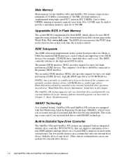
.... Built-In Diskette/Tape Drive Controller The OptiPlex GXa and OptiPlex NX systems are normally used to 128 MB, may be connected to two highperformance EIDE devices, typically EIDE tape drives or CD-ROM drives. All main memory is implemented in Chapter 2,"Basic Troubleshooting". The... start-up to the primary EIDE interface. The low-profile chassis can accommodate two external drive devices. 1-4 Dell OptiPlex GXa and OptiPlex NX Systems Service Manual Main Memory Main memory for the OptiPlex GXa and OptiPlex NX systems ranges from Dell's home page on the World Wide Web (www...
.... Built-In Diskette/Tape Drive Controller The OptiPlex GXa and OptiPlex NX systems are normally used to 128 MB, may be connected to two highperformance EIDE devices, typically EIDE tape drives or CD-ROM drives. All main memory is implemented in Chapter 2,"Basic Troubleshooting". The... start-up to the primary EIDE interface. The low-profile chassis can accommodate two external drive devices. 1-4 Dell OptiPlex GXa and OptiPlex NX Systems Service Manual Main Memory Main memory for the OptiPlex GXa and OptiPlex NX systems ranges from Dell's home page on the World Wide Web (www...

Service Manual
Page 17
...: • ATI 3D Rage Pro SVGA video controller • 2-MB synchronous graphics random-access memory (SGRAM) video memory (expandable to the Ethernet network through a single RJ45 connector on the back System Overview 1-5 Built-In SVGA Subsystem The OptiPlex GXa and OptiPlex NX systems include a built-in Ethernet NIC subsystem (optional if using the EM system...
...: • ATI 3D Rage Pro SVGA video controller • 2-MB synchronous graphics random-access memory (SGRAM) video memory (expandable to the Ethernet network through a single RJ45 connector on the back System Overview 1-5 Built-In SVGA Subsystem The OptiPlex GXa and OptiPlex NX systems include a built-in Ethernet NIC subsystem (optional if using the EM system...

Service Manual
Page 24
... any required memory space, IRQ lines, and DMA channels to an installed PCI expansion card during system start-up when DC power is applied to the riser board. Riser Board for Net PC Computer Low-Profile Computer's Expansion-Card Slots The OptiPlex GXa low-profile computers... slots. OptiPlex NX Computer's Expansion-Card Slot The OptiPlex NX computer has one ISA expansion-card connector share a single expansion-card slot, resulting in a total of the lowprofile computer, the riser board includes the P1 connector (for the Low-Profile Computer 1-12 Dell OptiPlex GXa and OptiPlex NX Systems...
... any required memory space, IRQ lines, and DMA channels to an installed PCI expansion card during system start-up when DC power is applied to the riser board. Riser Board for Net PC Computer Low-Profile Computer's Expansion-Card Slots The OptiPlex GXa low-profile computers... slots. OptiPlex NX Computer's Expansion-Card Slot The OptiPlex NX computer has one ISA expansion-card connector share a single expansion-card slot, resulting in a total of the lowprofile computer, the riser board includes the P1 connector (for the Low-Profile Computer 1-12 Dell OptiPlex GXa and OptiPlex NX Systems...

Service Manual
Page 28
...-performance microprocessor is accomplished by a system administrator at a remote location. 1-16 Dell OptiPlex GXa and OptiPlex NX Systems Service Manual Adding video memory increases the system's video performance and provides additional modes for the various chassis configurations...subsections provide service-related information about the computer. Microprocessor/L2 Cache Upgrades On the OptiPlex GXa and OptiPlex NX systems, the microprocessor and secondary L2 cache memory are provided for high-resolution/expanded color applications. Unless otherwise specified, the information...
...-performance microprocessor is accomplished by a system administrator at a remote location. 1-16 Dell OptiPlex GXa and OptiPlex NX Systems Service Manual Adding video memory increases the system's video performance and provides additional modes for the various chassis configurations...subsections provide service-related information about the computer. Microprocessor/L2 Cache Upgrades On the OptiPlex GXa and OptiPlex NX systems, the microprocessor and secondary L2 cache memory are provided for high-resolution/expanded color applications. Unless otherwise specified, the information...
Service Manual
Page 40
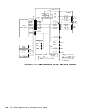
Figure 1-22. DC Power Distribution for the Low-Profile Computer 1-28 Dell OptiPlex GXa and OptiPlex NX Systems Service Manual system board +3 VDC battery P1 PWRGOOD POWER1 power RTC/ management NVRAM and NIC logic system power supply PSON# +5 VFP +5 VDC -5 ... VDC PCI1 PCI2 P1 (only on EM systems) ISA1 ISA2 optional P3 drive P4 3.5-inch diskette P5 internal hard-disk drive +12 VDC FAN main memory sockets DIMM_A DIMM_B DIMM_C +5 VFP +5 VDC +5 VDC fuses +5 VDC PANEL USB KYBD +5 VDC MICROPROCESSOR +3.3 VDC processor core regulator core VCC +2.1 to +3.5 VDC MOUSE NOTE...
Figure 1-22. DC Power Distribution for the Low-Profile Computer 1-28 Dell OptiPlex GXa and OptiPlex NX Systems Service Manual system board +3 VDC battery P1 PWRGOOD POWER1 power RTC/ management NVRAM and NIC logic system power supply PSON# +5 VFP +5 VDC -5 ... VDC PCI1 PCI2 P1 (only on EM systems) ISA1 ISA2 optional P3 drive P4 3.5-inch diskette P5 internal hard-disk drive +12 VDC FAN main memory sockets DIMM_A DIMM_B DIMM_C +5 VFP +5 VDC +5 VDC fuses +5 VDC PANEL USB KYBD +5 VDC MICROPROCESSOR +3.3 VDC processor core regulator core VCC +2.1 to +3.5 VDC MOUSE NOTE...

Service Manual
Page 42
... ISA3 +12 VDC FAN internal P2 hard-disk drive internal P3 hard-disk drive P4 3.5-inch diskette drive P5* optional drive P6* optional drive main memory sockets DIMM_A DIMM_B DIMM_C +5 VFP +5 VDC PANEL +5 VDC +5 VDC USB KYBD fuses (2) +5 VDC MICROPROCESSOR processor core regulator +3.3 VDC core VCC +2.1 to +3.5 VDC MOUSE NOTE: On... board. * Some computers have an additional connector (P9) that may be used instead of P5 or P6. DC Power Distribution for the Midsize Computer 1-30 Dell OptiPlex GXa and OptiPlex NX Systems Service Manual Figure 1-24.
... ISA3 +12 VDC FAN internal P2 hard-disk drive internal P3 hard-disk drive P4 3.5-inch diskette drive P5* optional drive P6* optional drive main memory sockets DIMM_A DIMM_B DIMM_C +5 VFP +5 VDC PANEL +5 VDC +5 VDC USB KYBD fuses (2) +5 VDC MICROPROCESSOR processor core regulator +3.3 VDC core VCC +2.1 to +3.5 VDC MOUSE NOTE: On... board. * Some computers have an additional connector (P9) that may be used instead of P5 or P6. DC Power Distribution for the Midsize Computer 1-30 Dell OptiPlex GXa and OptiPlex NX Systems Service Manual Figure 1-24.

Service Manual
Page 43
... hard-disk drive internal P3 hard-disk drive P4 3.5-inch diskette drive P5 optional drive P6 optional drive P9 optional drive +12 VDC FAN main memory sockets DIMM_A DIMM_B DIMM_C +5 VFP +5 VDC PANEL +5 VDC +5 VDC USB KYBD +5 VDC MICROPROCESSOR processor core regulator +3.3 VDC core VCC +2.1 to +3.5 VDC MOUSE NOTE: On EM...
... hard-disk drive internal P3 hard-disk drive P4 3.5-inch diskette drive P5 optional drive P6 optional drive P9 optional drive +12 VDC FAN main memory sockets DIMM_A DIMM_B DIMM_C +5 VFP +5 VDC PANEL +5 VDC +5 VDC USB KYBD +5 VDC MICROPROCESSOR processor core regulator +3.3 VDC core VCC +2.1 to +3.5 VDC MOUSE NOTE: On EM...
Service Manual
Page 47
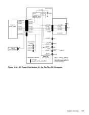
Figure 1-30. DC Power Distribution for the OptiPlex NX Computer System Overview 1-35 system board +3 VDC power management RTC/ and NIC logic NVRAM battery computer power supply P1 PWRGOOD PSON# +5 VFP POWER_1 PSON# +5 ... +5 VDC +12 VDC -12 VDC RISER +3.3 VDC +5 VDC +12 VDC -12 VDC riser board P1 PCI1 internal P3 hard-disk drive +12 VDC FAN main memory sockets DIMM_A DIMM_B DIMM_C +5 VFP +5 VDC PANEL +5 VDC USB +5 VDC KYBD fuses (2) +5 VDC MICROPROCESSOR processor core regulator +3.3 VDC core VCC +2.1 to +3.5 VDC MOUSE NOTE: +5VFP...
Figure 1-30. DC Power Distribution for the OptiPlex NX Computer System Overview 1-35 system board +3 VDC power management RTC/ and NIC logic NVRAM battery computer power supply P1 PWRGOOD PSON# +5 VFP POWER_1 PSON# +5 ... +5 VDC +12 VDC -12 VDC RISER +3.3 VDC +5 VDC +12 VDC -12 VDC riser board P1 PCI1 internal P3 hard-disk drive +12 VDC FAN main memory sockets DIMM_A DIMM_B DIMM_C +5 VFP +5 VDC PANEL +5 VDC USB +5 VDC KYBD fuses (2) +5 VDC MICROPROCESSOR processor core regulator +3.3 VDC core VCC +2.1 to +3.5 VDC MOUSE NOTE: +5VFP...

Service Manual
Page 49
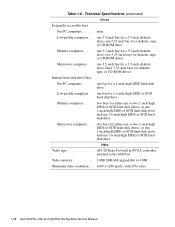
... (on standard system board) or optional on enhanced manageability system board; 3Com PCI 3C905 network controller, operating at 10 or 100 Mbps Memory Architecture 64-bit (nonparity) or 72-bit (parity), noninterleaved DIMM sockets three (gold contacts) DIMM capacities 16- two (one ISA ... . . and 32-MB nonparity SDRAM; 32-, 64-, and 128-MB parity SDRAM Standard RAM 16 MB Maximum RAM 384 MB L2 cache memory 512-MB pipeline-burst, four-way set-associative, write-back SRAM BIOS address F0000h System Overview 1-37 Technical Specifications (continued) Expansion Bus (continued...
... (on standard system board) or optional on enhanced manageability system board; 3Com PCI 3C905 network controller, operating at 10 or 100 Mbps Memory Architecture 64-bit (nonparity) or 72-bit (parity), noninterleaved DIMM sockets three (gold contacts) DIMM capacities 16- two (one ISA ... . . and 32-MB nonparity SDRAM; 32-, 64-, and 128-MB parity SDRAM Standard RAM 16 MB Maximum RAM 384 MB L2 cache memory 512-MB pipeline-burst, four-way set-associative, write-back SRAM BIOS address F0000h System Overview 1-37 Technical Specifications (continued) Expansion Bus (continued...
Service Manual
Page 50
... Video Video type ATI 3D Rage Pro built-in SVGA controller attached to the AGP bus Video memory 2-MB SGRAM, upgradable to 4 MB Maximum video resolution . . . 1600 x 1200 pixels, with 256 colors 1-38 Dell OptiPlex GXa and OptiPlex NX Systems Service Manual two 5.25-inch bays for a 3.5-inch diskette drive; three 5.25-inch bays for...
... Video Video type ATI 3D Rage Pro built-in SVGA controller attached to the AGP bus Video memory 2-MB SGRAM, upgradable to 4 MB Maximum video resolution . . . 1600 x 1200 pixels, with 256 colors 1-38 Dell OptiPlex GXa and OptiPlex NX Systems Service Manual two 5.25-inch bays for a 3.5-inch diskette drive; three 5.25-inch bays for...
Service Manual
Page 60
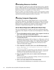
...press to restore the default settings, or press and the right-arrow key to boot from the network. Running Computer Diagnostics The OptiPlex GXa systems use either diskette-based or server-based (EM systems only) diagnostics. Highlight the Boot Sequence field (see a menu to..., follow these steps: 1. Then move the LANDesk Service Agent above drive C: on system access. 2-6 Dell OptiPlex GXa and OptiPlex NX Systems Service Manual Because a device may require dedicated memory spaces, interrupt levels, or DMA channels, all of which must be installed at a different time, it...
...press to restore the default settings, or press and the right-arrow key to boot from the network. Running Computer Diagnostics The OptiPlex GXa systems use either diskette-based or server-based (EM systems only) diagnostics. Highlight the Boot Sequence field (see a menu to..., follow these steps: 1. Then move the LANDesk Service Agent above drive C: on system access. 2-6 Dell OptiPlex GXa and OptiPlex NX Systems Service Manual Because a device may require dedicated memory spaces, interrupt levels, or DMA channels, all of which must be installed at a different time, it...
Service Manual
Page 62
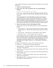
...detected, a message indicates which DIMM has failed. Checks the functionality of the mouse controller and the operation of the hard-disk drive 2-8 Dell OptiPlex GXa and OptiPlex NX Systems Service Manual age capability of the mouse keys • Hard-Disk Drive Tests - then shut down the system and try again... suspected hardware problem, run the hard-disk-based diagnostics, and if you wait too long and the operating system begins to load into memory, let the system complete the load operation; If no errors are prepared to open the computer, refer to "Internal Visual Inspection" found...
...detected, a message indicates which DIMM has failed. Checks the functionality of the mouse controller and the operation of the hard-disk drive 2-8 Dell OptiPlex GXa and OptiPlex NX Systems Service Manual age capability of the mouse keys • Hard-Disk Drive Tests - then shut down the system and try again... suspected hardware problem, run the hard-disk-based diagnostics, and if you wait too long and the operating system begins to load into memory, let the system complete the load operation; If no errors are prepared to open the computer, refer to "Internal Visual Inspection" found...
Service Manual
Page 64
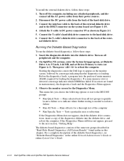
...-Disk-Based Diagnostics (All System Boards)" found in the online Network Administrator's Guide or online System User's Guide. 2-10 Dell OptiPlex GXa and OptiPlex NX Systems Service Manual Running the Diskette-Based Diagnostics To run the diskette-based diagnostics, follow these steps: 1. Then press to... the computer. 2. connect all tests for the Diagnostics Menu. Attach the Y-cable to Auto (see "Diskette-Based Diagnostics" in main memory, the diagnostics loads and the Diagnostics Menu appears. 3. nal diskette drive. Before the diagnostics loads, a program tests the portion of ...
...-Disk-Based Diagnostics (All System Boards)" found in the online Network Administrator's Guide or online System User's Guide. 2-10 Dell OptiPlex GXa and OptiPlex NX Systems Service Manual Running the Diskette-Based Diagnostics To run the diskette-based diagnostics, follow these steps: 1. Then press to... the computer. 2. connect all tests for the Diagnostics Menu. Attach the Y-cable to Auto (see "Diskette-Based Diagnostics" in main memory, the diagnostics loads and the Diagnostics Menu appears. 3. nal diskette drive. Before the diagnostics loads, a program tests the portion of ...


