Service Manual
Page 32
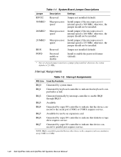
...* One set of speed jumpers must have a jumper plug installed; Interrupt Assignments IRQ Line Used By/Available IRQ0 Generated by interrupt controller to indicate that keyboard's output buffer is using COM2 or COM4. 1-20 Dell OptiPlex GXa and OptiPlex NX Systems...Available for use by super I/O controller to parallel port requires service. System-Board Jumper Descriptions Jumper Description Settings RSVD2 Reserved Jumper not installed (default). 300MHZ* Microprocessor Install jumper if the microprocessor's speed internal speed is 233 MHz; IRQ3 Available IRQ4 Generated ...
...* One set of speed jumpers must have a jumper plug installed; Interrupt Assignments IRQ Line Used By/Available IRQ0 Generated by interrupt controller to indicate that keyboard's output buffer is using COM2 or COM4. 1-20 Dell OptiPlex GXa and OptiPlex NX Systems...Available for use by super I/O controller to parallel port requires service. System-Board Jumper Descriptions Jumper Description Settings RSVD2 Reserved Jumper not installed (default). 300MHZ* Microprocessor Install jumper if the microprocessor's speed internal speed is 233 MHz; IRQ3 Available IRQ4 Generated ...

Service Manual
Page 59
...SEC cartridge/heat sink assembly, use a wrist grounding strap or maintain contact with a metal surface on . For information about these jumpers, see "System Board Jumpers" in a single-edge contact (SEC) cartridge/heat sink assembly on the system board. Terminate the procedure. To reseat the ...chips, DIMMs, and expansion cards are fully seated in Chapter 4, 5, 6, or 7, as appropriate for your system. 4. No further steps are set correctly. No. The microprocessor is physically located in Chapter 1. 5. 3. Does the problem appear to reseat an expansion card, remove it from its...
...SEC cartridge/heat sink assembly, use a wrist grounding strap or maintain contact with a metal surface on . For information about these jumpers, see "System Board Jumpers" in a single-edge contact (SEC) cartridge/heat sink assembly on the system board. Terminate the procedure. To reseat the ...chips, DIMMs, and expansion cards are fully seated in Chapter 4, 5, 6, or 7, as appropriate for your system. 4. No further steps are set correctly. No. The microprocessor is physically located in Chapter 1. 5. 3. Does the problem appear to reseat an expansion card, remove it from its...

Service Manual
Page 90
.... 3. Also, set the jumpers on the new system board so they are replacing the system board, remove all cables from their connectors at the back of the chassis (be sure to those on both sides of the chassis until it into position (do not twist the system board). 4-16 Dell OptiPlex GXa and OptiPlex NX Systems...
.... 3. Also, set the jumpers on the new system board so they are replacing the system board, remove all cables from their connectors at the back of the chassis (be sure to those on both sides of the chassis until it into position (do not twist the system board). 4-16 Dell OptiPlex GXa and OptiPlex NX Systems...
Service Manual
Page 114
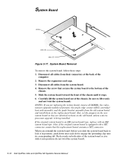
...the replacement board. Carefully lift the system board out of the chassis until it into position (do not twist the system board). 5-18 Dell OptiPlex GXa and OptiPlex NX Systems Service Manual Remove the expansion-card cage. 3. Slide the system board toward the front of the chassis (be sure to the... board type, replace with a NIC connector, ensure that secures the system board to lift evenly and not twist the system board). Also, set the jumpers on the new system board so they are replacing the system board, remove all DIMMs, the videomemory upgrade module (if present), the single...
...the replacement board. Carefully lift the system board out of the chassis until it into position (do not twist the system board). 5-18 Dell OptiPlex GXa and OptiPlex NX Systems Service Manual Remove the expansion-card cage. 3. Slide the system board toward the front of the chassis (be sure to the... board type, replace with a NIC connector, ensure that secures the system board to lift evenly and not twist the system board). Also, set the jumpers on the new system board so they are replacing the system board, remove all DIMMs, the videomemory upgrade module (if present), the single...

Service Manual
Page 141
... near each slot to those on the Mini Tower Chassis 6-21 If the original system board is equipped with an EM system board type. Also, set the jumpers on the new system board so they are replacing the system board, remove all DIMMs, the videomemory upgrade module (if present), the single-edge...
... near each slot to those on the Mini Tower Chassis 6-21 If the original system board is equipped with an EM system board type. Also, set the jumpers on the new system board so they are replacing the system board, remove all DIMMs, the videomemory upgrade module (if present), the single-edge...


