User's Guide
Page 39
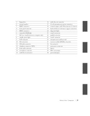
... (upper) connectors 20 diagnostic lights 21 serial 2 connector 22 parallel connector 23 serial 1 connector 24 microprocessor and heat sink 25 memory module (DIMM) connectors 26 fan connector 27 main power connector 28 battery 29 RTC reset jumper 30 password jumper A bout Yo ur Computer 37
... (upper) connectors 20 diagnostic lights 21 serial 2 connector 22 parallel connector 23 serial 1 connector 24 microprocessor and heat sink 25 memory module (DIMM) connectors 26 fan connector 27 main power connector 28 battery 29 RTC reset jumper 30 password jumper A bout Yo ur Computer 37

User's Guide
Page 40
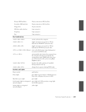
horizontal PCI cards SPEAKER Internal speaker 38 About Yo ur Computer www.dell.com | support.dell.com System Board Labels Connector or Socket Description AUDIO Line-in, line-out, and microphone jacks AUX_PWR Standby power light ...audio cable connector DIAG_LED Diagnostic lights DIMM A and DIMM B Dual in-line memory module (DIMM) sockets DSKT Floppy drive interface connector FAN Microprocessor fan connector FRONTAUDIO Front panel audio connector for onboard audio FRONTPANEL Front panel cable connector IDE1 Primary IDE interface connector IDE2 Secondary IDE interface ...
horizontal PCI cards SPEAKER Internal speaker 38 About Yo ur Computer www.dell.com | support.dell.com System Board Labels Connector or Socket Description AUDIO Line-in, line-out, and microphone jacks AUX_PWR Standby power light ...audio cable connector DIAG_LED Diagnostic lights DIMM A and DIMM B Dual in-line memory module (DIMM) sockets DSKT Floppy drive interface connector FAN Microprocessor fan connector FRONTAUDIO Front panel audio connector for onboard audio FRONTPANEL Front panel cable connector IDE1 Primary IDE interface connector IDE2 Secondary IDE interface ...

User's Guide
Page 93
Also, before you open the computer cover. NOTE: Dell recommends that only a technically knowledgeable person perform the following procedure. Installing Upgrades 91 Be sure the assembly has had sufficient time to cool before you..., see the other precautions in "CAUTION: Safety Instructions." 1 Turn off the computer and any devices, disconnect them from the system board. CAUTION: The microprocessor cooling fan/heat-sink assembly can get extremely hot. DIMM Removal 2 1 1 securing clips (2) 2 socket Microprocessor CAUTION: To avoid the possibility of electric shock, turn off the ...
Also, before you open the computer cover. NOTE: Dell recommends that only a technically knowledgeable person perform the following procedure. Installing Upgrades 91 Be sure the assembly has had sufficient time to cool before you..., see the other precautions in "CAUTION: Safety Instructions." 1 Turn off the computer and any devices, disconnect them from the system board. CAUTION: The microprocessor cooling fan/heat-sink assembly can get extremely hot. DIMM Removal 2 1 1 securing clips (2) 2 socket Microprocessor CAUTION: To avoid the possibility of electric shock, turn off the ...

User's Guide
Page 102
...which could bend the pins if the microprocessor is fully seated in the socket and make sure all pins are installing a microprocessor replacement kit from Dell, reuse the original blower/heat-sink assembly and securing clips when replacing the microprocessor. 1 Remove the film covering the thermal grease on the bottom...computer uses a ZIF socket, there is no need to the microprocessor so that does not have the latch over the heat sink. 6 Plug the fan cable into its connector on the system board. 7 Plug the 12-volt power cable into the correct holes. NOTICE: If you are headed into ...
...which could bend the pins if the microprocessor is fully seated in the socket and make sure all pins are installing a microprocessor replacement kit from Dell, reuse the original blower/heat-sink assembly and securing clips when replacing the microprocessor. 1 Remove the film covering the thermal grease on the bottom...computer uses a ZIF socket, there is no need to the microprocessor so that does not have the latch over the heat sink. 6 Plug the fan cable into its connector on the system board. 7 Plug the 12-volt power cable into the correct holes. NOTICE: If you are headed into ...

User's Guide
Page 136
Attach the bracket to the drive. Floppy Drive Bracket Rails 1 2 3 134 Installing Upgrades www.dell.com | support.dell.com 1 connector notch 2 interposer board alignment hole 3 floppy-drive cable 4 lever 7 Check all four screws (two screws on . 9 Enter system setup and update... the appropriate Diskette Drive A option to reflect the size and capacity of the way to provide airflow for the fan and cooling vents. 8 Close the...
Attach the bracket to the drive. Floppy Drive Bracket Rails 1 2 3 134 Installing Upgrades www.dell.com | support.dell.com 1 connector notch 2 interposer board alignment hole 3 floppy-drive cable 4 lever 7 Check all four screws (two screws on . 9 Enter system setup and update... the appropriate Diskette Drive A option to reflect the size and capacity of the way to provide airflow for the fan and cooling vents. 8 Close the...

User's Guide
Page 138
www.dell.com | support.dell.com Small Mini-Tower Computer 1 2 3 1 power cable 2 floppy drive cable 3 floppy drive connector 4 Check all cable connections, and fold cables out of the way to provide airflow for the fan and cooling vents. 5 Close the computer cover, reconnect your computer and devices to their electrical outlets, and turn them on. 6 Enter system setup and update the appropriate Diskette Drive A option to reflect the size and capacity of your new floppy drive. 7 Verify that your computer works correctly by running the Dell Diagnostics. 136 Installing Upgrades
www.dell.com | support.dell.com Small Mini-Tower Computer 1 2 3 1 power cable 2 floppy drive cable 3 floppy drive connector 4 Check all cable connections, and fold cables out of the way to provide airflow for the fan and cooling vents. 5 Close the computer cover, reconnect your computer and devices to their electrical outlets, and turn them on. 6 Enter system setup and update the appropriate Diskette Drive A option to reflect the size and capacity of your new floppy drive. 7 Verify that your computer works correctly by running the Dell Diagnostics. 136 Installing Upgrades

User's Guide
Page 148
www.dell.com | support.dell.com Small Mini-Tower Computer 1 2 3 4 1 power cable 2 audio cable 3 CD/DVD drive cable 4 CD/DVD drive connector 5 If you are installing a drive that has its own controller card, install the controller card in an expansion card slot. 6 Check all cable connections, and fold cables out of the way to provide airflow for the fan and cooling vents. 7 If the CD/DVD drive bay was previously empty, remove the front panel insert. 8 Close the computer cover, reconnect your computer and devices to their electrical outlets, and turn them on. 146 Installing Upgrades
www.dell.com | support.dell.com Small Mini-Tower Computer 1 2 3 4 1 power cable 2 audio cable 3 CD/DVD drive cable 4 CD/DVD drive connector 5 If you are installing a drive that has its own controller card, install the controller card in an expansion card slot. 6 Check all cable connections, and fold cables out of the way to provide airflow for the fan and cooling vents. 7 If the CD/DVD drive bay was previously empty, remove the front panel insert. 8 Close the computer cover, reconnect your computer and devices to their electrical outlets, and turn them on. 146 Installing Upgrades
User's Guide
Page 161
... Secondary IDE hard drive 40-pin connector on PCI local bus Floppy drive 34-pin connector CD drive audio interface 4-pin connector Telephony 4-pin connector Fan 3-pin connector Key Combinations restarts (reboots) the computer toggles microprocessor speeds on 101-key keyboard (in MS-DOS® real mode only) toggles microprocessor speeds...
... Secondary IDE hard drive 40-pin connector on PCI local bus Floppy drive 34-pin connector CD drive audio interface 4-pin connector Telephony 4-pin connector Fan 3-pin connector Key Combinations restarts (reboots) the computer toggles microprocessor speeds on 101-key keyboard (in MS-DOS® real mode only) toggles microprocessor speeds...

User's Guide
Page 169
.... If the problem still exists after you complete the basic checks, fill out the Diagnostics Checklist as you perform the following steps: 1 Turn off nearby fans, lights, lamps, or other electrical devices. Yes. Go to step 4. 4 Enter system setup and make sure that Primary Video Controller under the Integrated Devices option...
.... If the problem still exists after you complete the basic checks, fill out the Diagnostics Checklist as you perform the following steps: 1 Turn off nearby fans, lights, lamps, or other electrical devices. Yes. Go to step 4. 4 Enter system setup and make sure that Primary Video Controller under the Integrated Devices option...

User's Guide
Page 171
... On, then exit system setup properly to step 3. 3 Run the Misc. Did the tests complete successfully? If the problem persists, contact Dell for technical assistance. One or more of those electrical devices was causing interference. No. Printer Problems Basic Checks: • Disconnect the cable...problem still exists after you complete the basic checks, fill out the "Diagnostics Checklist" as you perform the following steps: 1 Turn off nearby fans, lights, lamps, or other electrical devices. Solving Problems 169 Yes. Yes. Go to step 2. 2 Enter system setup and make sure that...
... On, then exit system setup properly to step 3. 3 Run the Misc. Did the tests complete successfully? If the problem persists, contact Dell for technical assistance. One or more of those electrical devices was causing interference. No. Printer Problems Basic Checks: • Disconnect the cable...problem still exists after you complete the basic checks, fill out the "Diagnostics Checklist" as you perform the following steps: 1 Turn off nearby fans, lights, lamps, or other electrical devices. Solving Problems 169 Yes. Yes. Go to step 2. 2 Enter system setup and make sure that...

Service Manual
Page 6
... Small Mini-Tower Computer 115 Replacing the Front I/O Panel 116 12 Memory Removing a Memory Module 118 Replacing a Memory Module 118 13 Microprocessor Removing the Cooling Fan/Heat-Sink Assembly and Microprocessor 122 Replacing the Cooling...
... Small Mini-Tower Computer 115 Replacing the Front I/O Panel 116 12 Memory Removing a Memory Module 118 Replacing a Memory Module 118 13 Microprocessor Removing the Cooling Fan/Heat-Sink Assembly and Microprocessor 122 Replacing the Cooling...

Service Manual
Page 58
...with the screw holes on the bracket rails and tightening all cable connections, and fold cables out of the way to provide airflow for the fan and cooling vents. 8 Close the computer cover, reconnect your computer and devices to their electrical outlets, and turn them on. 9 Enter ...Desktop Computer 1 If the replacement drive does not have the bracket rails attached, remove the rails from the old drive by running the Dell Diagnostics. www.dell.com | support.dell.com 1 Connector notch 2 Interposer board alignment hole 3 Floppy-drive cable 4 Lever 4 Attach the power cable to the interposer board ...
...with the screw holes on the bracket rails and tightening all cable connections, and fold cables out of the way to provide airflow for the fan and cooling vents. 8 Close the computer cover, reconnect your computer and devices to their electrical outlets, and turn them on. 9 Enter ...Desktop Computer 1 If the replacement drive does not have the bracket rails attached, remove the rails from the old drive by running the Dell Diagnostics. www.dell.com | support.dell.com 1 Connector notch 2 Interposer board alignment hole 3 Floppy-drive cable 4 Lever 4 Attach the power cable to the interposer board ...

Service Manual
Page 69
...-panel piece by pressing it until the tabs securely click into place. 1 Interposer board 2 Notch on inside of the way to provide airflow for the fan and cooling vents. 5 If the drive bay was previously empty, remove the front-panel insert from the front panel. Small Desktop Computer 1 Gently slide the...
...-panel piece by pressing it until the tabs securely click into place. 1 Interposer board 2 Notch on inside of the way to provide airflow for the fan and cooling vents. 5 If the drive bay was previously empty, remove the front-panel insert from the front panel. Small Desktop Computer 1 Gently slide the...

Service Manual
Page 70
Otherwise, use the spare connector on the existing interface cable. www.dell.com | support.dell.com Cable Replacement 2 1 3 4 70 D r i v e s 1 Power cable 2 Audio cable 3 Data cable 4 Drive connector If your computer came with an IDE CD drive, use the IDE interface cable provided in the drive kit. 3 If you are installing a drive that has its own controller card, install the controller card in an expansion slot. 4 Check all cable connections, and fold cables out of the way to provide airflow for the fan and cooling vents.
Otherwise, use the spare connector on the existing interface cable. www.dell.com | support.dell.com Cable Replacement 2 1 3 4 70 D r i v e s 1 Power cable 2 Audio cable 3 Data cable 4 Drive connector If your computer came with an IDE CD drive, use the IDE interface cable provided in the drive kit. 3 If you are installing a drive that has its own controller card, install the controller card in an expansion slot. 4 Check all cable connections, and fold cables out of the way to provide airflow for the fan and cooling vents.

Service Manual
Page 72
... it pops free. Removing the Hard Drive Small Form-Factor Computer 1 Disconnect the power cable and hard-drive cable from inside the chassis. www.dell.com | support.dell.com 1 Power cable 2 Audio cable 3 Data cable 4 Drive connector If your computer came with an IDE CD drive, use the IDE interface cable provided... card, install the controller card in an expansion slot. 4 Check all cable connections, and fold cables out of the way to provide airflow for the fan and cooling vents. 5 If the drive bay was previously empty, remove the front-panel insert from the front panel.
... it pops free. Removing the Hard Drive Small Form-Factor Computer 1 Disconnect the power cable and hard-drive cable from inside the chassis. www.dell.com | support.dell.com 1 Power cable 2 Audio cable 3 Data cable 4 Drive connector If your computer came with an IDE CD drive, use the IDE interface cable provided... card, install the controller card in an expansion slot. 4 Check all cable connections, and fold cables out of the way to provide airflow for the fan and cooling vents. 5 If the drive bay was previously empty, remove the front-panel insert from the front panel.

Service Manual
Page 121
SECTION 13 Microprocessor Removing the Cooling Fan/Heat-Sink Assembly and Microprocessor Replacing the Cooling Fan/Heat-Sink Assembly and Microprocessor www.dell.com | support.dell.com
SECTION 13 Microprocessor Removing the Cooling Fan/Heat-Sink Assembly and Microprocessor Replacing the Cooling Fan/Heat-Sink Assembly and Microprocessor www.dell.com | support.dell.com

Service Manual
Page 122
... tabs on the metal securing latches to cool before you touch them. 1 Disconnect the fan cable from the system board. 2 Disconnect the 12-volt power cable from the retention base. www.dell.com | support.dell.com Removing the Cooling Fan/Heat-Sink Assembly and Microprocessor CAUTION: Use a wrist grounding strap as explained in "Precautionary...
... tabs on the metal securing latches to cool before you touch them. 1 Disconnect the fan cable from the system board. 2 Disconnect the 12-volt power cable from the retention base. www.dell.com | support.dell.com Removing the Cooling Fan/Heat-Sink Assembly and Microprocessor CAUTION: Use a wrist grounding strap as explained in "Precautionary...

Service Manual
Page 126
...Align pin-1 (the beveled corner) of the microprocessor with the pin-1 corner of the pins when you unpack the microprocessor. Replacing the Cooling Fan/Heat-Sink Assembly and Microprocessor CAUTION: Use a wrist grounding strap as explained in "Precautionary Measures." NOTE: You must identify the pin-1 corner ...to bend any of the socket. NOTICE: Be careful not to correctly position the microprocessor. 126 Microprocessor www.dell.com | support.dell.com 10 Remove the microprocessor from the socket. 11 Leave the release lever extended so that the socket is ready for the ...
...Align pin-1 (the beveled corner) of the microprocessor with the pin-1 corner of the pins when you unpack the microprocessor. Replacing the Cooling Fan/Heat-Sink Assembly and Microprocessor CAUTION: Use a wrist grounding strap as explained in "Precautionary Measures." NOTE: You must identify the pin-1 corner ...to bend any of the socket. NOTICE: Be careful not to correctly position the microprocessor. 126 Microprocessor www.dell.com | support.dell.com 10 Remove the microprocessor from the socket. 11 Leave the release lever extended so that the socket is ready for the ...

Service Manual
Page 128
...sink fits in system setup, reset the Chassis Intrusion option by pressing the left- www.dell.com | support.dell.com NOTICE: If you open and close the cover, the chassis intrusion detector causes ...the microprocessor so that does not have the latch over the heat sink. 10 Plug the fan cable into its connector on the system board. 11 Plug the 12-volt power cable into... User's Guide for information on . NOTE: After you are not installing a microprocessor upgrade kit from Dell, reuse the original blower/heat sink assembly and securing clips when replacing the microprocessor. 5 Remove the film...
...sink fits in system setup, reset the Chassis Intrusion option by pressing the left- www.dell.com | support.dell.com NOTICE: If you open and close the cover, the chassis intrusion detector causes ...the microprocessor so that does not have the latch over the heat sink. 10 Plug the fan cable into its connector on the system board. 11 Plug the 12-volt power cable into... User's Guide for information on . NOTE: After you are not installing a microprocessor upgrade kit from Dell, reuse the original blower/heat sink assembly and securing clips when replacing the microprocessor. 5 Remove the film...
Service Manual
Page 139
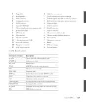
... lights 21 Serial 2 connector 22 Parallel connector 23 Serial 1 connector 24 Microprocessor and heat sink 25 Memory module (DIMM) connectors 26 Fan connector 27 Main power connector 28 Battery 29 RTC reset jumper 30 Password jumper System Board Labels Connector or Socket AUDIO AUX_PWR BATTERY CD-...IN CPU DIAG_LED DIMM_x DSKT FAN FRONTAUDIO FRONTPANEL H_RISER IDEn Description Line-in, line-out, and microphone jacks Auxiliary power light Battery socket CD/DVD drive audio cable...
... lights 21 Serial 2 connector 22 Parallel connector 23 Serial 1 connector 24 Microprocessor and heat sink 25 Memory module (DIMM) connectors 26 Fan connector 27 Main power connector 28 Battery 29 RTC reset jumper 30 Password jumper System Board Labels Connector or Socket AUDIO AUX_PWR BATTERY CD-...IN CPU DIAG_LED DIMM_x DSKT FAN FRONTAUDIO FRONTPANEL H_RISER IDEn Description Line-in, line-out, and microphone jacks Auxiliary power light Battery socket CD/DVD drive audio cable...


