Service Manual
Page 1
Removing and Replacing Parts Mini Tower Chassis - Dell Computer Corporation disclaims any manner whatsoever without notice. © 2000 Dell Computer Corporation. Removing and Replacing Parts Midsize Chassis - NOTICE: A NOTICE indicates either the entities claiming the marks and names or their... helps you how to avoid the problem. All rights reserved. Initial release: 18 April 2000 Last revised: 31 Jul 2000 Dell™ OptiPlex™ GX200 Service Manual Small Form-Factor Chassis - Information in trademarks and trade names other than its own. Reproduction in any proprietary interest...
Removing and Replacing Parts Mini Tower Chassis - Dell Computer Corporation disclaims any manner whatsoever without notice. © 2000 Dell Computer Corporation. Removing and Replacing Parts Midsize Chassis - NOTICE: A NOTICE indicates either the entities claiming the marks and names or their... helps you how to avoid the problem. All rights reserved. Initial release: 18 April 2000 Last revised: 31 Jul 2000 Dell™ OptiPlex™ GX200 Service Manual Small Form-Factor Chassis - Information in trademarks and trade names other than its own. Reproduction in any proprietary interest...
Service Manual
Page 38
Removing and Replacing Parts: Dell™ OptiPlex™ GX200 Systems Service Manual Overview Recommended Tools Precautionary Measures Internal Views Computer Cover Front Bezel Eject, Power, and Reset Buttons Front-Panel Inserts Control ...l Wide flat-blade screwdriver l #1 and #2 Phillips-head screwdrivers l 1/4-inch nut driver Also, use of one or more of the following steps in the Dell OptiPlex mini tower chassis GX200 system. Also, disconnect any of the procedures in this file, take a few moments to 20 seconds after disconnecting the computer from the computer. Precautionary...
Removing and Replacing Parts: Dell™ OptiPlex™ GX200 Systems Service Manual Overview Recommended Tools Precautionary Measures Internal Views Computer Cover Front Bezel Eject, Power, and Reset Buttons Front-Panel Inserts Control ...l Wide flat-blade screwdriver l #1 and #2 Phillips-head screwdrivers l 1/4-inch nut driver Also, use of one or more of the following steps in the Dell OptiPlex mini tower chassis GX200 system. Also, disconnect any of the procedures in this file, take a few moments to 20 seconds after disconnecting the computer from the computer. Precautionary...
Service Manual
Page 39
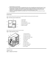
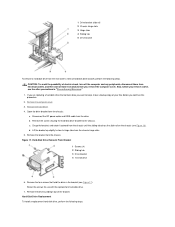
... the chassis. If it to discharge any unpainted metal surface on the back of computer Figure 2 shows the mini tower chassis with the cover removed. Computer Cover Removal Inside the Mini Tower Chassis 1 5.25-inch drive slots 2 Hard-disk drive bracket 3 Chassis intrusion switch 4 Hard-disk drive interface...or contacts on a card and avoid touching pins on . Wear a wrist grounding strap, and clip it is on the back of the mini tower chassis computer to go out (see Riser Boards). Verify that might harm internal components. Figure 2. Figure 1. If a wrist grounding strap is not on...
... the chassis. If it to discharge any unpainted metal surface on the back of computer Figure 2 shows the mini tower chassis with the cover removed. Computer Cover Removal Inside the Mini Tower Chassis 1 5.25-inch drive slots 2 Hard-disk drive bracket 3 Chassis intrusion switch 4 Hard-disk drive interface...or contacts on a card and avoid touching pins on . Wear a wrist grounding strap, and clip it is on the back of the mini tower chassis computer to go out (see Riser Boards). Verify that might harm internal components. Figure 2. Figure 1. If a wrist grounding strap is not on...
Service Manual
Page 40
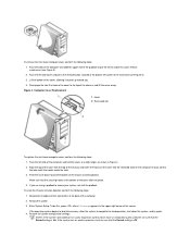
... are using a padlock to unlock the cover release mechanism (see Figure 3). 3. Computer Cover Replacement 1 Hook 2 Recessed slot To replace the mini tower computer cover, perform the following steps: 1. Make sure that the Sound setting is Off. Restart the system. 3. Enter System Setup. Restore the ..., located at a slight angle, as shown in the upper-right corner of the front bezel (see Figure 3). 2. To remove the mini tower computer cover, perform the following steps: 1. Lift the bottom of the computer. 2. Disengage the tabs that the Sound setting is On. To...
... are using a padlock to unlock the cover release mechanism (see Figure 3). 3. Computer Cover Replacement 1 Hook 2 Recessed slot To replace the mini tower computer cover, perform the following steps: 1. Make sure that the Sound setting is Off. Restart the system. 3. Enter System Setup. Restore the ..., located at a slight angle, as shown in the upper-right corner of the front bezel (see Figure 3). 2. To remove the mini tower computer cover, perform the following steps: 1. Lift the bottom of the computer. 2. Disengage the tabs that the Sound setting is On. To...

Service Manual
Page 41
...Off. 6. While in System Setup, press and follow the menu directions to configure the system if it has an LS-120 SuperDisk drive: a. Run the Dell Diagnostics to Not Installed. Disengage the two retaining hooks at the bottom of the bezel. 3. Carefully pull the bezel away from the chassis. 2. Fit ... the tabs on the top of the chassis snap into their slots on the bezel into their corresponding slots at the bottom of the mini tower chassis. 2. While pressing the tab release marked with the icon, tilt the bezel away from the chassis. While in System Setup, perform the following ...
...Off. 6. While in System Setup, press and follow the menu directions to configure the system if it has an LS-120 SuperDisk drive: a. Run the Dell Diagnostics to Not Installed. Disengage the two retaining hooks at the bottom of the bezel. 3. Carefully pull the bezel away from the chassis. 2. Fit ... the tabs on the top of the chassis snap into their slots on the bezel into their corresponding slots at the bottom of the mini tower chassis. 2. While pressing the tab release marked with the icon, tilt the bezel away from the chassis. While in System Setup, perform the following ...
Service Manual
Page 47
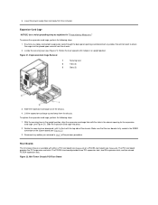
... a replacement hard-disk drive, perform the following steps. If you remove the computer cover. d. Disconnect the DC power cable and EIDE cable from the mini tower's internal hard-disk drive bracket, perform the following steps. Figure 17. Remove the front bezel. 4. Remove the four screws that contains data you want to...
... a replacement hard-disk drive, perform the following steps. If you remove the computer cover. d. Disconnect the DC power cable and EIDE cable from the mini tower's internal hard-disk drive bracket, perform the following steps. Figure 17. Remove the front bezel. 4. Remove the four screws that contains data you want to...
Service Manual
Page 50
..., until it is fully seated in the chassis opening for the expansion- Riser Boards The mini tower chassis is available with the slots in the RISER connector on the system board (see Figure 21). Mini Tower Chassis PCI Riser Board Lower the power supply down and away from the chassis. Slide the...
..., until it is fully seated in the chassis opening for the expansion- Riser Boards The mini tower chassis is available with the slots in the RISER connector on the system board (see Figure 21). Mini Tower Chassis PCI Riser Board Lower the power supply down and away from the chassis. Slide the...
Service Manual
Page 51
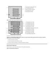
... and connectors. 1 Auxiliary power indicator (AUX_LED) 2 PCI expansion slot 5 (PCI5) 3 Wake On LAN (WOL) connector 4 PCI expansion slot 1 (PCI1) 5 Auxiliary power connector Figure 23. Mini Tower Chassis PCI/ISA Riser Board 1 PCI expansion slot 1 (PCI1) 2 PCI expansion slot 2 (PCI2) 3 PCI expansion slot 3 (PCI3) 4 PCI expansion slot 4 (PCI4) 5 ISA expansion slot 1 (ISA1...
... and connectors. 1 Auxiliary power indicator (AUX_LED) 2 PCI expansion slot 5 (PCI5) 3 Wake On LAN (WOL) connector 4 PCI expansion slot 1 (PCI1) 5 Auxiliary power connector Figure 23. Mini Tower Chassis PCI/ISA Riser Board 1 PCI expansion slot 1 (PCI1) 2 PCI expansion slot 2 (PCI2) 3 PCI expansion slot 3 (PCI3) 4 PCI expansion slot 4 (PCI4) 5 ISA expansion slot 1 (ISA1...


