Service Manual
Page 2
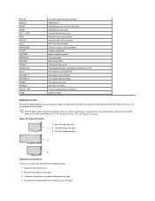
.... l You can replace or reinstall a part by performing the removal procedure in the Dell OptiPlex low-profile chassis GX200 system. If you perform any telephone or telecommunication lines from the electrical outlet before disconnecting the...OptiPlex™ GX200 Systems Service Manual Overview Recommended Tools Precautionary Measures Internal Views Computer Cover Eject, Power, and Reset Buttons Front-Panel Inserts Control Panel Chassis Intrusion Switch Drives System Power Supply Expansion-Card Cage Riser Boards System Board Components Expansion Cards Memory Microprocessor/Cooling Fan...
.... l You can replace or reinstall a part by performing the removal procedure in the Dell OptiPlex low-profile chassis GX200 system. If you perform any telephone or telecommunication lines from the electrical outlet before disconnecting the...OptiPlex™ GX200 Systems Service Manual Overview Recommended Tools Precautionary Measures Internal Views Computer Cover Eject, Power, and Reset Buttons Front-Panel Inserts Control Panel Chassis Intrusion Switch Drives System Power Supply Expansion-Card Cage Riser Boards System Board Components Expansion Cards Memory Microprocessor/Cooling Fan...
Service Manual
Page 10
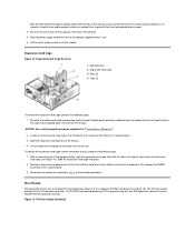
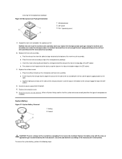
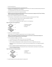
... until it is important to where the cage must be placed upon removal from being pinched or crimped. 3. Figure 15. Remove the screw below the fan guard on the system board. 3. Lift the power supply up and away from the system board and drives. Rotate the lever upward until it stops...
... until it is important to where the cage must be placed upon removal from being pinched or crimped. 3. Figure 15. Remove the screw below the fan guard on the system board. 3. Lift the power supply up and away from the system board and drives. Rotate the lever upward until it stops...
Service Manual
Page 12
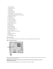
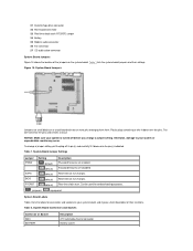
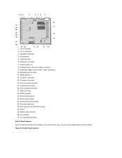
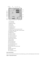
... board jumpers 21 Diskette/tape-drive connector 22 Riser board connector 23 Real-time clock reset (RTCRST) jumper 24 Battery 25 Modem audio connector 26 Fan connector 27 CD audio cable connector System Board Jumpers Figure 18 shows the location of the jumpers on a circuit board with two or more pins...
... board jumpers 21 Diskette/tape-drive connector 22 Riser board connector 23 Real-time clock reset (RTCRST) jumper 24 Battery 25 Modem audio connector 26 Fan connector 27 CD audio cable connector System Board Jumpers Figure 18 shows the location of the jumpers on a circuit board with two or more pins...
Service Manual
Page 13
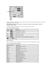
...socket CD-ROM audio interface connector RIMM socket Diskette/tape drive interface connector Integrated NIC connector External speaker connector Microprocessor fan connector Hard-disk drive LED connector EIDE interface connector Chassis intrusion switch connector Keyboard connector Modem audio connector Video ...power input connector 3.3-V power input connector Riser board connector Serial port connector Primary microprocessor connector USB connectors Expansion Cards Each GX200 low-profile chassis can accommodate 32-bit PCI expansion cards and 16-bit and 8-bit ISA expansion cards, depending on ...
...socket CD-ROM audio interface connector RIMM socket Diskette/tape drive interface connector Integrated NIC connector External speaker connector Microprocessor fan connector Hard-disk drive LED connector EIDE interface connector Chassis intrusion switch connector Keyboard connector Modem audio connector Video ...power input connector 3.3-V power input connector Riser board connector Serial port connector Primary microprocessor connector USB connectors Expansion Cards Each GX200 low-profile chassis can accommodate 32-bit PCI expansion cards and 16-bit and 8-bit ISA expansion cards, depending on ...
Service Manual
Page 16
...lever-type handle that the socket is released. Figure 25. To replace a microprocessor, perform the following steps: 1. Disconnect the cooling fan power cable from the microprocessor package. NOTICE: Be careful not to cool before you remove the microprocessor package from the ZIF socket. Leave... extremely hot. Pull the socket release lever straight out until the microprocessor package is ready for the new microprocessor. a. b. NOTE: Dell recommends that secures the heat sink assembly to the microprocessor package by gently pushing down on the folded part of the retaining clip with...
...lever-type handle that the socket is released. Figure 25. To replace a microprocessor, perform the following steps: 1. Disconnect the cooling fan power cable from the microprocessor package. NOTICE: Be careful not to cool before you remove the microprocessor package from the ZIF socket. Leave... extremely hot. Pull the socket release lever straight out until the microprocessor package is ready for the new microprocessor. a. b. NOTE: Dell recommends that secures the heat sink assembly to the microprocessor package by gently pushing down on the folded part of the retaining clip with...
Service Manual
Page 18
... front of the chassis until it out of its socket with your fingers or with the "+" facing up. Remove the RIMMs and the microprocessor/cooling fan/heat sink assembly, and install them on the old board, unless you replace the system battery, orient the new battery with a blunt, nonconducting object such...
... front of the chassis until it out of its socket with your fingers or with the "+" facing up. Remove the RIMMs and the microprocessor/cooling fan/heat sink assembly, and install them on the old board, unless you replace the system battery, orient the new battery with a blunt, nonconducting object such...
Service Manual
Page 29
... Battery socket 21 Diskette/tape-drive connector 22 Riser board connector 23 Real-time clock reset (RTCRST) jumper 24 Battery 25 Modem audio connector 26 Fan connector 27 CD audio cable connector System Board Jumpers Figure 15 shows the location of their settings. Plastic plugs containing a wire fit down onto the...
... Battery socket 21 Diskette/tape-drive connector 22 Riser board connector 23 Real-time clock reset (RTCRST) jumper 24 Battery 25 Modem audio connector 26 Fan connector 27 CD audio cable connector System Board Jumpers Figure 15 shows the location of their settings. Plastic plugs containing a wire fit down onto the...
Service Manual
Page 30
...any cables connected to remove. For the location of this LED, see Figures 19 and 20. CD_IN RIMM_x DSKT ENET EXT_SPKR FAN HDLED IDEn INTRUDER KYBD MODEM MONITOR MOUSE PANEL PARALLEL PCIn* POWER_1 POWER_2 RISER SERIALn SLOT1_PRI USB CD-ROM audio interface connector RIMM... socket Diskette/tape drive interface connector Integrated NIC connector External speaker connector Microprocessor fan connector Hard-disk drive LED connector EIDE interface connector Chassis intrusion switch connector Keyboard connector Modem audio connector Video connector Mouse...
...any cables connected to remove. For the location of this LED, see Figures 19 and 20. CD_IN RIMM_x DSKT ENET EXT_SPKR FAN HDLED IDEn INTRUDER KYBD MODEM MONITOR MOUSE PANEL PARALLEL PCIn* POWER_1 POWER_2 RISER SERIALn SLOT1_PRI USB CD-ROM audio interface connector RIMM... socket Diskette/tape drive interface connector Integrated NIC connector External speaker connector Microprocessor fan connector Hard-disk drive LED connector EIDE interface connector Chassis intrusion switch connector Keyboard connector Modem audio connector Video connector Mouse...
Service Manual
Page 35
...the ZIF socket. Place the heat sink assembly on the top edge of the shroud and lower it is not enough thermal compound between the fan and the power supply bracket on the bottom edge of the clip to the bottom of microprocessor installed. Replace the airflow shroud. Discard used ...batteries according to overheat because there is incorrectly installed. Rotate the power supply back into the alignment slot on the left side of the fan and between the old heat sink assembly and the microprocessor package. 10. Figure 26. Press down on the hinged end of the ZIF socket....
...the ZIF socket. Place the heat sink assembly on the top edge of the shroud and lower it is not enough thermal compound between the fan and the power supply bracket on the bottom edge of the clip to the bottom of microprocessor installed. Replace the airflow shroud. Discard used ...batteries according to overheat because there is incorrectly installed. Rotate the power supply back into the alignment slot on the left side of the fan and between the old heat sink assembly and the microprocessor package. 10. Figure 26. Press down on the hinged end of the ZIF socket....
Service Manual
Page 52
... board jumpers 21 Diskette/tape-drive connector 22 Riser board connector 23 Real-time clock reset (RTCRST) jumper 24 Battery 25 Modem audio connector 26 Fan connector 27 CD audio cable connector System Board Jumpers Figure 25 shows the location of the jumpers on the system board. Table 1 lists the system...
... board jumpers 21 Diskette/tape-drive connector 22 Riser board connector 23 Real-time clock reset (RTCRST) jumper 24 Battery 25 Modem audio connector 26 Fan connector 27 CD audio cable connector System Board Jumpers Figure 25 shows the location of the jumpers on the system board. Table 1 lists the system...
Service Manual
Page 53
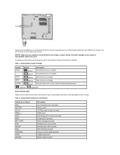
...or more pins emerging from them. System Board Connectors and Sockets Connector or Socket AMC BATTERY CD_IN RIMM_x DSKT ENET EXT_SPKR FAN HDLED IDEn INTRUDER KYBD MODEM Description ATI multimedia channel connector Battery socket CD-ROM audio interface connector RIMM socket Diskette/tape... drive interface connector Integrated NIC connector External speaker connector Microprocessor fan connector Hard-disk drive LED connector EIDE interface connector Chassis intrusion switch connector Keyboard connector Modem audio connector Reserved (do ...
...or more pins emerging from them. System Board Connectors and Sockets Connector or Socket AMC BATTERY CD_IN RIMM_x DSKT ENET EXT_SPKR FAN HDLED IDEn INTRUDER KYBD MODEM Description ATI multimedia channel connector Battery socket CD-ROM audio interface connector RIMM socket Diskette/tape... drive interface connector Integrated NIC connector External speaker connector Microprocessor fan connector Hard-disk drive LED connector EIDE interface connector Chassis intrusion switch connector Keyboard connector Modem audio connector Reserved (do ...
Service Manual
Page 58
... headed into place, securing the microprocessor package. d. Replace the airflow shroud. Rotate the power supply back into the chassis tabs located above the system cooling fan. Replace the computer cover. 14. NOTICE: You must position the microprocessor package correctly in the ZIF socket. When the microprocessor package is positioned correctly, press...
... headed into place, securing the microprocessor package. d. Replace the airflow shroud. Rotate the power supply back into the chassis tabs located above the system cooling fan. Replace the computer cover. 14. NOTICE: You must position the microprocessor package correctly in the ZIF socket. When the microprocessor package is positioned correctly, press...
Service Manual
Page 61
...Also, disconnect any procedures in this manual require the use a wrist grounding strap as explained in the Dell OptiPlex small formfactor chassis GX200 system. Doing so reduces the potential for removing and replacing the components, assemblies, and subassemblies in "...OptiPlex™ GX200 Systems Service Manual Overview Recommended Tools Precautionary Measures Internal Views Computer Cover Eject and Power Buttons Control Panel Chassis Intrusion Switch Drives System Power Supply Expansion-Card Cage Riser Board System Board Components Expansion Cards Memory Microprocessor/Cooling Fan...
...Also, disconnect any procedures in this manual require the use a wrist grounding strap as explained in the Dell OptiPlex small formfactor chassis GX200 system. Doing so reduces the potential for removing and replacing the components, assemblies, and subassemblies in "...OptiPlex™ GX200 Systems Service Manual Overview Recommended Tools Precautionary Measures Internal Views Computer Cover Eject and Power Buttons Control Panel Chassis Intrusion Switch Drives System Power Supply Expansion-Card Cage Riser Board System Board Components Expansion Cards Memory Microprocessor/Cooling Fan...

Service Manual
Page 70
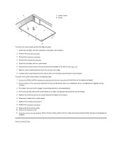
... Auto. Lift the power supply up and out of the computer approximately 1 inch. 6. Expansion-Card Cage Removal See the online System User's Guide for the fan and cooling vents. 3. Expansion-Card Cage Figure 18. Disconnect the AC power cable from the system board and the drives. 3. Slide the power supply toward...
... Auto. Lift the power supply up and out of the computer approximately 1 inch. 6. Expansion-Card Cage Removal See the online System User's Guide for the fan and cooling vents. 3. Expansion-Card Cage Figure 18. Disconnect the AC power cable from the system board and the drives. 3. Slide the power supply toward...
Service Manual
Page 72
... board jumpers 21 Diskette/tape-drive connector 22 Riser board connector 23 Real-time clock reset (RTCRST) jumper 24 Battery 25 Modem audio connector 26 Fan connector 27 CD audio cable connector System Board Jumpers Figure 21 shows the location of the jumpers on the system board.
... board jumpers 21 Diskette/tape-drive connector 22 Riser board connector 23 Real-time clock reset (RTCRST) jumper 24 Battery 25 Modem audio connector 26 Fan connector 27 CD audio cable connector System Board Jumpers Figure 21 shows the location of the jumpers on the system board.
Service Manual
Page 73
...). Real-time clock reset. System Board Connectors and Sockets Connector or Socket AMC BATTERY CD_IN RIMM_x DSKT ENET EXT_SPKR FAN HDLED IDEn INTRUDER KYBD MODEM MONITOR Description ATI multimedia channel connector Battery socket CD-ROM audio interface connector RIMM socket Diskette.../tape drive interface connector Integrated NIC connector External speaker connector Microprocessor fan connector Hard-disk drive LED connector EIDE interface connector Chassis intrusion switch connector Keyboard connector Modem audio connector Video ...
...). Real-time clock reset. System Board Connectors and Sockets Connector or Socket AMC BATTERY CD_IN RIMM_x DSKT ENET EXT_SPKR FAN HDLED IDEn INTRUDER KYBD MODEM MONITOR Description ATI multimedia channel connector Battery socket CD-ROM audio interface connector RIMM socket Diskette.../tape drive interface connector Integrated NIC connector External speaker connector Microprocessor fan connector Hard-disk drive LED connector EIDE interface connector Chassis intrusion switch connector Keyboard connector Modem audio connector Video ...

Service Manual
Page 76
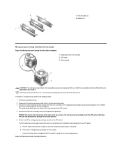
...Replace the computer cover. 5. Figure 26. Microprocessor/Cooling Fan/Heat Sink Assembly 1 Cooling fan/heat sink assembly 2 ZIF socket 3 Retaining clip CAUTION: The microprocessor/heat sink assembly can get extremely hot. NOTE: Dell recommends that the RIMMs are operating properly. Locate the plastic... securing clips at each end of the socket until they snap open. 3. Microprocessor/Cooling Fan/Heat Sink Assembly Figure 27. 1 Securing clips (2)...
...Replace the computer cover. 5. Figure 26. Microprocessor/Cooling Fan/Heat Sink Assembly 1 Cooling fan/heat sink assembly 2 ZIF socket 3 Retaining clip CAUTION: The microprocessor/heat sink assembly can get extremely hot. NOTE: Dell recommends that the RIMMs are operating properly. Locate the plastic... securing clips at each end of the socket until they snap open. 3. Microprocessor/Cooling Fan/Heat Sink Assembly Figure 27. 1 Securing clips (2)...
Service Manual
Page 77
...screwdriver. Bending the pins can permanently damage the microprocessor. 5. The ZIF socket has a lever-type handle that secures the cooling fan/heat sink assembly to the microprocessor and the computer when you remove the microprocessor package from the ZIF socket. Remove the microprocessor package.... 3. Unpack the new microprocessor package. Microprocessor Package Installation 1 Microprocessor 2 ZIF socket 3 Pin-1 (beveled corner) 8. Unpack the cooling fan/heat sink assembly included in the ZIF socket. Figure 28. If any of the pins when you turn on the folded part of the...
...screwdriver. Bending the pins can permanently damage the microprocessor. 5. The ZIF socket has a lever-type handle that secures the cooling fan/heat sink assembly to the microprocessor and the computer when you remove the microprocessor package from the ZIF socket. Remove the microprocessor package.... 3. Unpack the new microprocessor package. Microprocessor Package Installation 1 Microprocessor 2 ZIF socket 3 Pin-1 (beveled corner) 8. Unpack the cooling fan/heat sink assembly included in the ZIF socket. Figure 28. If any of the pins when you turn on the folded part of the...

Service Manual
Page 78
... or equivalent type recommended by carefully prying it out of the new battery exploding if it into its system board connector. 11. Reconnect the cooling fan power cable to snap the clip over the tab on the bottom edge of the ZIF socket. System Board Removal Reset the chassis intrusion detector...
... or equivalent type recommended by carefully prying it out of the new battery exploding if it into its system board connector. 11. Reconnect the cooling fan power cable to snap the clip over the tab on the bottom edge of the ZIF socket. System Board Removal Reset the chassis intrusion detector...
Service Manual
Page 79
... drive shelf assembly. 3. Remove the screw that they are identical to Contents Page Reset the chassis intrusion detector. Remove the RIMMs and the microprocessor/cooling fan/heat sink assembly and install them on both sides of the computer. 2. Replace the hard-disk drive/bracket. 8. 1 System board 2 Screw To remove the system...
... drive shelf assembly. 3. Remove the screw that they are identical to Contents Page Reset the chassis intrusion detector. Remove the RIMMs and the microprocessor/cooling fan/heat sink assembly and install them on both sides of the computer. 2. Replace the hard-disk drive/bracket. 8. 1 System board 2 Screw To remove the system...


