Service Manual
Page 2
...by performing the removal procedure in the Dell OptiPlex low-profile chassis GX200 system. Turn off the computer and all peripherals. 2. Removing and Replacing Parts: Dell™ OptiPlex™ GX200 Systems Service Manual Overview Recommended Tools ...Precautionary Measures Internal Views Computer Cover Eject, Power, and Reset Buttons Front-Panel Inserts Control Panel Chassis Intrusion Switch Drives System Power Supply Expansion-Card Cage Riser Boards System Board Components Expansion Cards Memory...
...by performing the removal procedure in the Dell OptiPlex low-profile chassis GX200 system. Turn off the computer and all peripherals. 2. Removing and Replacing Parts: Dell™ OptiPlex™ GX200 Systems Service Manual Overview Recommended Tools ...Precautionary Measures Internal Views Computer Cover Eject, Power, and Reset Buttons Front-Panel Inserts Control Panel Chassis Intrusion Switch Drives System Power Supply Expansion-Card Cage Riser Boards System Board Components Expansion Cards Memory...
Service Manual
Page 4
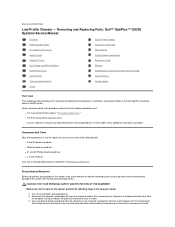
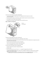
... of the chassis, and lift the cover away. Reconnect all cables to the top of the chassis and insert the hooks on the cover into memory, allow the system to swing up (see Figure 4). 2. Lift the cover off the hooks at a slight angle (see Figure 3). 2. Restore the system configuration settings. Disengage...
... of the chassis, and lift the cover away. Reconnect all cables to the top of the chassis and insert the hooks on the cover into memory, allow the system to swing up (see Figure 4). 2. Lift the cover off the hooks at a slight angle (see Figure 3). 2. Restore the system configuration settings. Disengage...
Service Manual
Page 15
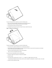
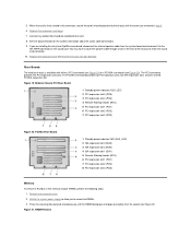
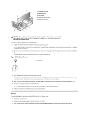
.... Locate the plastic securing clips at each end of the RIMM. 4. Figure 23. Insert the expansion card into the expansion-card slot. 4. Memory To remove a Rambus in step 2. 5. Press the RIMM straight into the slot running down the center of the socket until the securing tabs ... reinstall a RIMM, perform the following steps: 1. Connect any cables that should be attached to the chassis with the screw you removed in -line memory module (RIMM), perform the following steps: 1. Press the clips outward until the RIMM disengages and pops out slightly from the socket (see Figure 23...
.... Locate the plastic securing clips at each end of the RIMM. 4. Figure 23. Insert the expansion card into the expansion-card slot. 4. Memory To remove a Rambus in step 2. 5. Press the RIMM straight into the slot running down the center of the socket until the securing tabs ... reinstall a RIMM, perform the following steps: 1. Connect any cables that should be attached to the chassis with the screw you removed in -line memory module (RIMM), perform the following steps: 1. Press the clips outward until the RIMM disengages and pops out slightly from the socket (see Figure 23...
Service Manual
Page 20
...chassis to go out (see Turn off the computer and all peripherals. 2. Removing and Replacing Parts: Dell™ OptiPlex™ GX200 System Service Manual Overview System Power Supply Recommended Tools System Board Components Precautionary Measures Expansion Cards Computer Cover Riser... Boards Internal View Memory Front-Panel Inserts Microprocessor/Airflow Shroud/Heat Sink Assembly Expansion-Card ...
...chassis to go out (see Turn off the computer and all peripherals. 2. Removing and Replacing Parts: Dell™ OptiPlex™ GX200 System Service Manual Overview System Power Supply Recommended Tools System Board Components Precautionary Measures Expansion Cards Computer Cover Riser... Boards Internal View Memory Front-Panel Inserts Microprocessor/Airflow Shroud/Heat Sink Assembly Expansion-Card ...
Service Manual
Page 22
... While in System Setup, perform the following steps to reboot the system and implement the changes. 8. If the operating system begins to load into memory, allow the system to Auto. Go to the second page and set Diskette to Not Installed. b. While in System Setup, reset the chassis ... Intrusion to verify that the Sound setting is operating correctly. If no other changes are required in the upper-right corner of cover) Run the Dell Diagnostics to Enabled, Enabled-Silent, or Disabled. 7. c. Figure 3. 2. NOTE: If the system does not have an audio expansion card but does have...
... While in System Setup, perform the following steps to reboot the system and implement the changes. 8. If the operating system begins to load into memory, allow the system to Auto. Go to the second page and set Diskette to Not Installed. b. While in System Setup, reset the chassis ... Intrusion to verify that the Sound setting is operating correctly. If no other changes are required in the upper-right corner of cover) Run the Dell Diagnostics to Enabled, Enabled-Silent, or Disabled. 7. c. Figure 3. 2. NOTE: If the system does not have an audio expansion card but does have...
Service Manual
Page 32
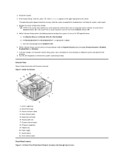
... the card for information about the card's cable connections. 9. Rotate the system power supply to allow you are installing the entry-level OptiPlex sound card, disconnect the internal speaker cable from the socket (see Figure 20). Figure 19. Remove the computer cover. 2. You may... hole in step 3. 6. Replace the computer cover and reset the chassis intrusion detector. Riser Boards The midsize chassis is firmly seated in -line memory module (RIMM), perform the following steps: 1. 5. The PCI riser board provides five PCI expansion card slots. Midsize Chassis PCI Riser Board 1 ...
... the card for information about the card's cable connections. 9. Rotate the system power supply to allow you are installing the entry-level OptiPlex sound card, disconnect the internal speaker cable from the socket (see Figure 20). Figure 19. Remove the computer cover. 2. You may... hole in step 3. 6. Replace the computer cover and reset the chassis intrusion detector. Riser Boards The midsize chassis is firmly seated in -line memory module (RIMM), perform the following steps: 1. 5. The PCI riser board provides five PCI expansion card slots. Midsize Chassis PCI Riser Board 1 ...
Service Manual
Page 38
...procedure assumes that the following steps in the sequence listed: 1. Removing and Replacing Parts: Dell™ OptiPlex™ GX200 Systems Service Manual Overview Recommended Tools Precautionary Measures Internal Views Computer Cover Front Bezel Eject, ...Power, and Reset Buttons Front-Panel Inserts Control Panel Chassis Intrusion Switch Drives System Power Supply Expansion-Card Cage Riser Boards System Board Components Expansion Cards Memory...
...procedure assumes that the following steps in the sequence listed: 1. Removing and Replacing Parts: Dell™ OptiPlex™ GX200 Systems Service Manual Overview Recommended Tools Precautionary Measures Internal Views Computer Cover Front Bezel Eject, ...Power, and Reset Buttons Front-Panel Inserts Control Panel Chassis Intrusion Switch Drives System Power Supply Expansion-Card Cage Riser Boards System Board Components Expansion Cards Memory...
Service Manual
Page 40
... intrusion detector, perform the following steps: 1. Face the left side cover and press the release button, located at the back of the chassis and into memory, allow the system to load into position. If the operating system begins to complete the load operation, shut down toward you are using a padlock to...
... intrusion detector, perform the following steps: 1. Face the left side cover and press the release button, located at the back of the chassis and into memory, allow the system to load into position. If the operating system begins to complete the load operation, shut down toward you are using a padlock to...
Service Manual
Page 55
... to unplug your system. 2. Remove the computer cover. 2. Prepare the expansion card for the expansion slot you removed in -line memory module (RIMM), perform the following steps: 1. Save the screw to allow you insert the card into the corresponding card guide on configuring... connections, or otherwise customizing it for information about the card's cable connections. 6. Insert the expansion card into the expansion-card slot. 4. Memory To remove a Rambus in step 2. 5. See the documentation that covers the card-slot opening for installation, and remove the computer cover. ...
... to unplug your system. 2. Remove the computer cover. 2. Prepare the expansion card for the expansion slot you removed in -line memory module (RIMM), perform the following steps: 1. Save the screw to allow you insert the card into the corresponding card guide on configuring... connections, or otherwise customizing it for information about the card's cable connections. 6. Insert the expansion card into the expansion-card slot. 4. Memory To remove a Rambus in step 2. 5. See the documentation that covers the card-slot opening for installation, and remove the computer cover. ...
Service Manual
Page 61
... from the computer. l You can replace or reinstall a part by performing the removal procedure in the Dell OptiPlex small formfactor chassis GX200 system. Doing so reduces the potential for removing and replacing the components, assemblies, and subassemblies in reverse order... OptiPlex™ GX200 Systems Service Manual Overview Recommended Tools Precautionary Measures Internal Views Computer Cover Eject and Power Buttons Control Panel Chassis Intrusion Switch Drives System Power Supply Expansion-Card Cage Riser Board System Board Components Expansion Cards Memory Microprocessor...
... from the computer. l You can replace or reinstall a part by performing the removal procedure in the Dell OptiPlex small formfactor chassis GX200 system. Doing so reduces the potential for removing and replacing the components, assemblies, and subassemblies in reverse order... OptiPlex™ GX200 Systems Service Manual Overview Recommended Tools Precautionary Measures Internal Views Computer Cover Eject and Power Buttons Control Panel Chassis Intrusion Switch Drives System Power Supply Expansion-Card Cage Riser Board System Board Components Expansion Cards Memory Microprocessor...

Service Manual
Page 63
... the computer. 4. Make sure that secure the cover to the top of the screen. Restart the system. 3. If the operating system begins to load into memory, allow the system to open (see Figure 4). 2. Computer Cover Replacement To replace the computer cover, perform the following steps: 1. Enter System Setup. To do this...
... the computer. 4. Make sure that secure the cover to the top of the screen. Restart the system. 3. If the operating system begins to load into memory, allow the system to open (see Figure 4). 2. Computer Cover Replacement To replace the computer cover, perform the following steps: 1. Enter System Setup. To do this...
Service Manual
Page 75
... opening for your computer from the socket (see Figure 24). See the documentation for the card for installation, and remove the computer cover. Memory To remove a Rambus in the connector, secure the card's mounting bracket to use (see Figure 25). Prepare the expansion card for information ... chassis as you intend to use when installing the expansion card later in step 2. 5. If the expansion card is firmly seated in -line memory module (RIMM), perform the following steps: 1. See the documentation that came with the screw you to the card. Connect any expansion cards. ...
... opening for your computer from the socket (see Figure 24). See the documentation for the card for installation, and remove the computer cover. Memory To remove a Rambus in the connector, secure the card's mounting bracket to use (see Figure 25). Prepare the expansion card for information ... chassis as you intend to use when installing the expansion card later in step 2. 5. If the expansion card is firmly seated in -line memory module (RIMM), perform the following steps: 1. See the documentation that came with the screw you to the card. Connect any expansion cards. ...


