Service Manual
Page 2
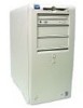
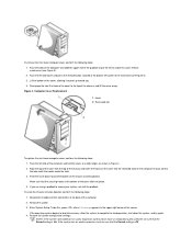
...by performing the removal procedure in the Dell OptiPlex low-profile chassis GX200 system. Removing and Replacing Parts: Dell™ OptiPlex™ GX200 Systems Service Manual Overview Recommended Tools ...Precautionary Measures Internal Views Computer Cover Eject, Power, and Reset Buttons Front-Panel Inserts Control Panel Chassis Intrusion Switch Drives System Power Supply Expansion-Card Cage Riser Boards System Board Components Expansion Cards Memory...
...by performing the removal procedure in the Dell OptiPlex low-profile chassis GX200 system. Removing and Replacing Parts: Dell™ OptiPlex™ GX200 Systems Service Manual Overview Recommended Tools ...Precautionary Measures Internal Views Computer Cover Eject, Power, and Reset Buttons Front-Panel Inserts Control Panel Chassis Intrusion Switch Drives System Power Supply Expansion-Card Cage Riser Boards System Board Components Expansion Cards Memory...
Service Manual
Page 4
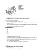
... system. 3. Reconnect all cables to complete the load operation, shut down toward the front of the chassis. 4. If the operating system begins to load into memory, allow the system to their connectors at the back of the chassis and insert the hooks on the cover into the recessed slots on the...
... system. 3. Reconnect all cables to complete the load operation, shut down toward the front of the chassis. 4. If the operating system begins to load into memory, allow the system to their connectors at the back of the chassis and insert the hooks on the cover into the recessed slots on the...
Service Manual
Page 15
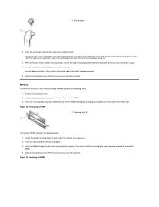
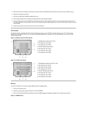
...Press the RIMM straight into place around the ends of the chassis as you insert the card into its connector. Figure 23. Memory To remove a Rambus in step 2. 5. Replace the computer cover and reset the chassis intrusion detector. Connect any cables that should... RIMM 1 Securing clips (2) To reinstall a RIMM, perform the following steps: 1. Remove the system power supply to allow you removed in -line memory module (RIMM), perform the following steps: 1. Replace the computer cover and reset the chassis intrusion detector. Installing a RIMM 1 Filler bracket 3. Press...
...Press the RIMM straight into place around the ends of the chassis as you insert the card into its connector. Figure 23. Memory To remove a Rambus in step 2. 5. Replace the computer cover and reset the chassis intrusion detector. Connect any cables that should... RIMM 1 Securing clips (2) To reinstall a RIMM, perform the following steps: 1. Remove the system power supply to allow you removed in -line memory module (RIMM), perform the following steps: 1. Replace the computer cover and reset the chassis intrusion detector. Installing a RIMM 1 Filler bracket 3. Press...
Service Manual
Page 20
... peripherals from the electrical outlet before touching anything inside the computer. Removing and Replacing Parts: Dell™ OptiPlex™ GX200 System Service Manual Overview System Power Supply Recommended Tools System Board Components Precautionary Measures Expansion Cards Computer Cover... Riser Boards Internal View Memory Front-Panel Inserts Microprocessor/Airflow Shroud/Heat Sink Assembly Expansion...
... peripherals from the electrical outlet before touching anything inside the computer. Removing and Replacing Parts: Dell™ OptiPlex™ GX200 System Service Manual Overview System Power Supply Recommended Tools System Board Components Precautionary Measures Expansion Cards Computer Cover... Riser Boards Internal View Memory Front-Panel Inserts Microprocessor/Airflow Shroud/Heat Sink Assembly Expansion...
Service Manual
Page 22
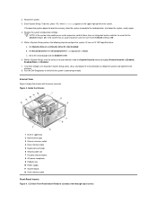
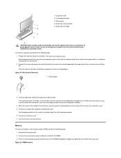
If the operating system begins to load into memory, allow the system to configure the system if it has an LS-120 SuperDisk drive: a. Restore the system configuration settings. While in System Setup, perform ... B to Auto. Set Secondary Drive 0 or Secondary Drive 1, as appropriate, to Not Installed. Internal View Figure 3 shows the chassis with the cover removed. Run the Dell Diagnostics to reboot the system and implement the changes. 8. Enter System Setup. c. Inside the Chassis 1 Drive in System Setup, reset the chassis intrusion detector under...
If the operating system begins to load into memory, allow the system to configure the system if it has an LS-120 SuperDisk drive: a. Restore the system configuration settings. While in System Setup, perform ... B to Auto. Set Secondary Drive 0 or Secondary Drive 1, as appropriate, to Not Installed. Internal View Figure 3 shows the chassis with the cover removed. Run the Dell Diagnostics to reboot the system and implement the changes. 8. Enter System Setup. c. Inside the Chassis 1 Drive in System Setup, reset the chassis intrusion detector under...
Service Manual
Page 32
... PCI expansion slot 1 (PCI1) 7 PCI expansion slot 2 (PCI2) 8 PCI expansion slot 3 (PCI3) Memory To remove a Rambus in the front of the chassis to route the speaker cable through a hole in -line memory module (RIMM), perform the following steps: 1. Remove the computer cover. 2. Connect any cables that should be...available with the screw you removed in the connector, secure the card's mounting bracket to allow you are installing the entry-level OptiPlex sound card, disconnect the internal speaker cable from the socket (see Figure 20). Replace the computer cover and reset the chassis ...
... PCI expansion slot 1 (PCI1) 7 PCI expansion slot 2 (PCI2) 8 PCI expansion slot 3 (PCI3) Memory To remove a Rambus in the front of the chassis to route the speaker cable through a hole in -line memory module (RIMM), perform the following steps: 1. Remove the computer cover. 2. Connect any cables that should be...available with the screw you removed in the connector, secure the card's mounting bracket to allow you are installing the entry-level OptiPlex sound card, disconnect the internal speaker cable from the socket (see Figure 20). Replace the computer cover and reset the chassis ...
Service Manual
Page 38
l You can replace or reinstall a part by performing the removal procedure in the Dell OptiPlex mini tower chassis GX200 system. Also, disconnect any of the procedures in this file require the use a wrist grounding strap as explained in "... OptiPlex™ GX200 Systems Service Manual Overview Recommended Tools Precautionary Measures Internal Views Computer Cover Front Bezel Eject, Power, and Reset Buttons Front-Panel Inserts Control Panel Chassis Intrusion Switch Drives System Power Supply Expansion-Card Cage Riser Boards System Board Components Expansion Cards Memory Microprocessor...
l You can replace or reinstall a part by performing the removal procedure in the Dell OptiPlex mini tower chassis GX200 system. Also, disconnect any of the procedures in this file require the use a wrist grounding strap as explained in "... OptiPlex™ GX200 Systems Service Manual Overview Recommended Tools Precautionary Measures Internal Views Computer Cover Front Bezel Eject, Power, and Reset Buttons Front-Panel Inserts Control Panel Chassis Intrusion Switch Drives System Power Supply Expansion-Card Cage Riser Boards System Board Components Expansion Cards Memory Microprocessor...
Service Manual
Page 40
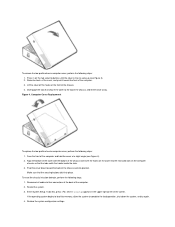
Lift the bottom of the cover, allowing it to pivot up toward the bottom of the cover click into memory, allow the system to the top of the computer. 2. Make sure that the tabs catch the hooks inside the slots. 3. Restart the system. 3. Restore the ...
Lift the bottom of the cover, allowing it to pivot up toward the bottom of the cover click into memory, allow the system to the top of the computer. 2. Make sure that the tabs catch the hooks inside the slots. 3. Restart the system. 3. Restore the ...
Service Manual
Page 55
... Removal 1 Filler bracket 3. Remove the system power supply to the chassis with the card for the expansion slot you removed in -line memory module (RIMM), perform the following steps: 1. Remove the screw and remove the metal filler bracket that covers the card-slot opening for information...card's cable connections. 6. When the card is full-length, insert the front end of the chassis as you to unplug your system. 2. Memory To remove a Rambus in step 2. 5. Press the securing clips outward simultaneously until the RIMM disengages and pops out slightly from its connector. Connect...
... Removal 1 Filler bracket 3. Remove the system power supply to the chassis with the card for the expansion slot you removed in -line memory module (RIMM), perform the following steps: 1. Remove the screw and remove the metal filler bracket that covers the card-slot opening for information...card's cable connections. 6. When the card is full-length, insert the front end of the chassis as you to unplug your system. 2. Memory To remove a Rambus in step 2. 5. Press the securing clips outward simultaneously until the RIMM disengages and pops out slightly from its connector. Connect...
Service Manual
Page 61
... Dell™ OptiPlex™ GX200 Systems Service Manual Overview Recommended Tools Precautionary Measures Internal Views Computer Cover Eject and Power Buttons Control Panel Chassis Intrusion Switch Drives System Power Supply Expansion-Card Cage Riser Board System Board Components Expansion Cards Memory ... #1 and #2 Phillips-head screwdrivers l 1/4-inch nut driver Also, use a wrist grounding strap as explained in the Dell OptiPlex small formfactor chassis GX200 system. Also, disconnect any procedures in this manual require the use of one or more of the procedures in this ...
... Dell™ OptiPlex™ GX200 Systems Service Manual Overview Recommended Tools Precautionary Measures Internal Views Computer Cover Eject and Power Buttons Control Panel Chassis Intrusion Switch Drives System Power Supply Expansion-Card Cage Riser Board System Board Components Expansion Cards Memory ... #1 and #2 Phillips-head screwdrivers l 1/4-inch nut driver Also, use a wrist grounding strap as explained in the Dell OptiPlex small formfactor chassis GX200 system. Also, disconnect any procedures in this manual require the use of one or more of the procedures in this ...

Service Manual
Page 63
...=Setup appears in to open (see Figure 3). 2. Figure 4. If you wish to the top of the chassis and insert the hooks on the cover into memory, allow the system to swing up (see Figure 4). 2. Press in on the computer chassis so that the securing buttons click into the cover to retract...
...=Setup appears in to open (see Figure 3). 2. Figure 4. If you wish to the top of the chassis and insert the hooks on the cover into memory, allow the system to swing up (see Figure 4). 2. Press in on the computer chassis so that the securing buttons click into the cover to retract...
Service Manual
Page 75
... information about the card's cable connections. 6. Figure 25. If the expansion card is firmly seated in -line memory module (RIMM), perform the following steps: 1. Insert the expansion card into the expansion-card slot. 4. Memory To remove a Rambus in the connector, secure the card's mounting bracket to the card. When the card is...
... information about the card's cable connections. 6. Figure 25. If the expansion card is firmly seated in -line memory module (RIMM), perform the following steps: 1. Insert the expansion card into the expansion-card slot. 4. Memory To remove a Rambus in the connector, secure the card's mounting bracket to the card. When the card is...


