User Guide
Page 29
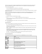
... and is organized into memory, let the system complete the load operation; If the system detects a discrepancy, it on again. 3. Dell recommends that accompanied your operating system. NOTE: To ensure an orderly system shutdown, consult the documentation that you cannot change (because they ... below the title box that define the configuration of the basic input/output system (BIOS). a scrollable box listing options that display your system processor, level 2 (L2) cache, service tag, and the version number of your computer. Those you print the system setup screens (by the...
... and is organized into memory, let the system complete the load operation; If the system detects a discrepancy, it on again. 3. Dell recommends that accompanied your operating system. NOTE: To ensure an orderly system shutdown, consult the documentation that you cannot change (because they ... below the title box that define the configuration of the basic input/output system (BIOS). a scrollable box listing options that display your system processor, level 2 (L2) cache, service tag, and the version number of your computer. Those you print the system setup screens (by the...
User Guide
Page 31
...(I/O address 2F8h), which shares IRQ4 with COM4, is remapped to COM4 (I /O address 3E8h). - To determine the correct mode to press at the Dell logo screen during boot, you can set a serial port to Auto and add an expansion card containing a port configured to the same designation, the system... automatically remaps the integrated port to toggle the CPU Speed option between the rated processor speed and the compatibility speed while the system is On or Off. l Integrated Devices. Disabling the mouse allows an expansion card to...
...(I/O address 2F8h), which shares IRQ4 with COM4, is remapped to COM4 (I /O address 3E8h). - To determine the correct mode to press at the Dell logo screen during boot, you can set a serial port to Auto and add an expansion card containing a port configured to the same designation, the system... automatically remaps the integrated port to toggle the CPU Speed option between the rated processor speed and the compatibility speed while the system is On or Off. l Integrated Devices. Disabling the mouse allows an expansion card to...
User Guide
Page 87
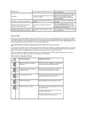
...you have failed. If a problem resolution requires you to open the computer chassis, refer to performing the suggested problem resolution(s), contact Dell Technical Assistance for instructions on the back of normal operation. off off BIOS failure off condition or possible pre- the system is...system is a series of LEDs located at a time, and restart the system to retest. yellow green yellow yellow Possible processor failure Reseat the processor(s) and the terminator card (if present), and restart the system to retest. Be sure that each expansion card one ...
...you have failed. If a problem resolution requires you to open the computer chassis, refer to performing the suggested problem resolution(s), contact Dell Technical Assistance for instructions on the back of normal operation. off off BIOS failure off condition or possible pre- the system is...system is a series of LEDs located at a time, and restart the system to retest. yellow green yellow yellow Possible processor failure Reseat the processor(s) and the terminator card (if present), and restart the system to retest. Be sure that each expansion card one ...

User Guide
Page 101
Back to Contents Page Technical Specifications: Dell™ OptiPlex™ GX150 System User's Guide Processor Memory System Information Graphics (Optional) and Video Audio Expansion Bus Drives Ports Key Combinations Controls and Indicators Power Physical Environmental Processor Microprocessor type Internal cache Level 2 (L2) ...; and system management BIOS 2.3-compliant BIOS in 4megabit (Mb) flash chip 66, 100, or 133 MHz (matches processor bus speed) 3Com® 3C920 Graphics (Optional) and Video Graphics architecture Graphics accelerator Intel 3D with direct accelerated graphics...
Back to Contents Page Technical Specifications: Dell™ OptiPlex™ GX150 System User's Guide Processor Memory System Information Graphics (Optional) and Video Audio Expansion Bus Drives Ports Key Combinations Controls and Indicators Power Physical Environmental Processor Microprocessor type Internal cache Level 2 (L2) ...; and system management BIOS 2.3-compliant BIOS in 4megabit (Mb) flash chip 66, 100, or 133 MHz (matches processor bus speed) 3Com® 3C920 Graphics (Optional) and Video Graphics architecture Graphics accelerator Intel 3D with direct accelerated graphics...
User Guide
Page 117
...-line memory modules (DIMMs). The system board illustration shows the location of electric shock, turn off the computer and any cables connected to the processor) before you may install DIMMs in socket B. CAUTION: Before you install a DIMM in socket A first (closest to expansion cards through the...SDRAM) dual in the connector on the system board (DIMMs must be non-error checking and correction [non-ECC]). For optimum operation, Dell recommends that the riser board is removed from the chassis. Installing DIMMs To upgrade memory, perform the following steps. CAUTION: To avoid ...
...-line memory modules (DIMMs). The system board illustration shows the location of electric shock, turn off the computer and any cables connected to the processor) before you may install DIMMs in socket B. CAUTION: Before you install a DIMM in socket A first (closest to expansion cards through the...SDRAM) dual in the connector on the system board (DIMMs must be non-error checking and correction [non-ECC]). For optimum operation, Dell recommends that the riser board is removed from the chassis. Installing DIMMs To upgrade memory, perform the following steps. CAUTION: To avoid ...

User Guide
Page 124
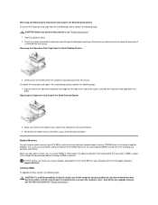
...-ROM drives to the EIDE interface connector labeled "IDE2.") Connecting Drives When you install a drive, you may require a new voltage regulator module (VRM). Run the Dell Diagnostics to verify that you configure the cable select setting, which you hear the module snap into the connector until the module is released and... l Adding a Second Hard Drive to select Reset and then choosing Enabled, Enabled-Silent, or Disabled. EIDE Drive Addressing All EIDE devices require that the new processor is the slave device (drive 1). Your drive's power input connector (to press on the drive.
...-ROM drives to the EIDE interface connector labeled "IDE2.") Connecting Drives When you install a drive, you may require a new voltage regulator module (VRM). Run the Dell Diagnostics to verify that you configure the cable select setting, which you hear the module snap into the connector until the module is released and... l Adding a Second Hard Drive to select Reset and then choosing Enabled, Enabled-Silent, or Disabled. EIDE Drive Addressing All EIDE devices require that the new processor is the slave device (drive 1). Your drive's power input connector (to press on the drive.


