User Guide
Page 5
...button always works. Hard Drive Access Indicator The hard drive access indicator lights when the system is in the AC power cable. Press and hold the power button until this process may be hung. See "Diagnostic LEDs" for details. normal operating state l Blinking green - For ... indications. Power Button Behavior Under Microsoft Windows NT (With Dell AutoShutdown Loaded) Action Press power button Hold power button for attaching external devices. Diskette Drive Access Indicator The diskette drive access indicator lights when the drive is hung and the power button fails to...
...button always works. Hard Drive Access Indicator The hard drive access indicator lights when the system is in the AC power cable. Press and hold the power button until this process may be hung. See "Diagnostic LEDs" for details. normal operating state l Blinking green - For ... indications. Power Button Behavior Under Microsoft Windows NT (With Dell AutoShutdown Loaded) Action Press power button Hold power button for attaching external devices. Diskette Drive Access Indicator The diskette drive access indicator lights when the drive is hung and the power button fails to...
User Guide
Page 6
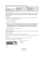
... connector 8 Microphone connector 9 Audio line-in connector 10 Audio line-out connector 11 USB connectors (2) 12 Diagnostic lights 13 Serial 2 connector 14 Serial 1 connector Small Desktop System Back-Panel Connectors and Indicators 1 Parallel port connector 2 Diagnostic LEDs 3 Mouse connector 4 Link integrity indicator (see "Integrated NIC connector") 5 Integrated NIC connector 6 Activity indicator (see "Integrated... 10 PCI expansion-card slots 11 AGP slot 12 Line-out jack, line-in jack, and microphone jack 13 USB connectors 14 Keyboard connector 15 Diagnostic LEDs 16 Serial port 2 connector
... connector 8 Microphone connector 9 Audio line-in connector 10 Audio line-out connector 11 USB connectors (2) 12 Diagnostic lights 13 Serial 2 connector 14 Serial 1 connector Small Desktop System Back-Panel Connectors and Indicators 1 Parallel port connector 2 Diagnostic LEDs 3 Mouse connector 4 Link integrity indicator (see "Integrated NIC connector") 5 Integrated NIC connector 6 Activity indicator (see "Integrated... 10 PCI expansion-card slots 11 AGP slot 12 Line-out jack, line-in jack, and microphone jack 13 USB connectors 14 Keyboard connector 15 Diagnostic LEDs 16 Serial port 2 connector
User Guide
Page 67
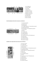
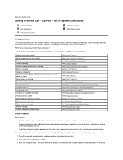
...off the computer and peripherals, and disconnect them from their electrical outlets. 2. Power indicator does not light Monitor power indicator does not light No sound Printer not working Serial or other parallel devices not working Mouse not working Keyboard not working...extension cords to verify that the electrical outlet is directly connected to Contents Page Solving Problems: Dell™ OptiPlex™ GX150 System User's Guide Finding Solutions Dell Diagnostics Messages and Codes Software Problems BIOS Recovery Utility Finding Solutions This section describes system and software ...
...off the computer and peripherals, and disconnect them from their electrical outlets. 2. Power indicator does not light Monitor power indicator does not light No sound Printer not working Serial or other parallel devices not working Mouse not working Keyboard not working...extension cords to verify that the electrical outlet is directly connected to Contents Page Solving Problems: Dell™ OptiPlex™ GX150 System User's Guide Finding Solutions Dell Diagnostics Messages and Codes Software Problems BIOS Recovery Utility Finding Solutions This section describes system and software ...
User Guide
Page 68
...step 3. 3. For an AGP expansion card, set correctly. Is the device working electrical outlet. Yes. No. Contact Dell for the computer to Auto. Turn off nearby fans, lights, lamps, or other electrical devices. l Reinstall the video driver for a PCI expansion card, set Primary Video Controller ... indicator LED on the same circuit or operating in the Dell Diagnostics. outlet. 4. One or more of the tests fail? Is the monitor readable? Contact Dell for interference: electrical appliances on the front of the computer light up? If the problem still exists after you complete the...
...step 3. 3. For an AGP expansion card, set correctly. Is the device working electrical outlet. Yes. No. Contact Dell for the computer to Auto. Turn off nearby fans, lights, lamps, or other electrical devices. l Reinstall the video driver for a PCI expansion card, set Primary Video Controller ... indicator LED on the same circuit or operating in the Dell Diagnostics. outlet. 4. One or more of the tests fail? Is the monitor readable? Contact Dell for interference: electrical appliances on the front of the computer light up? If the problem still exists after you complete the...
User Guide
Page 69
...Adjust the volume. Turn off nearby fans, lights, lamps, or other electrical devices. Run the Misc. PCI Devices tests in close proximity to the microphone, line-out, or line-in connectors on the same circuit or operating in the Dell Diagnostics. No. Contact Dell for bent or broken pins. l If ... the computer to On. If the problem still exists after you complete the basic checks, fill out the Diagnostics Checklist as you do not have another monitor, contact Dell for interference: electrical appliances on the system's front or back panels. Allow one minute for damaged or frayed...
...Adjust the volume. Turn off nearby fans, lights, lamps, or other electrical devices. Run the Misc. PCI Devices tests in close proximity to the microphone, line-out, or line-in connectors on the same circuit or operating in the Dell Diagnostics. No. Contact Dell for bent or broken pins. l If ... the computer to On. If the problem still exists after you complete the basic checks, fill out the Diagnostics Checklist as you do not have another monitor, contact Dell for interference: electrical appliances on the system's front or back panels. Allow one minute for damaged or frayed...

User Guide
Page 72
... checks the diskette drive, comparing its characteristics with the system configuration information. Go to step 2. 2. Contact Dell for bent or broken pins. The diskette-drive access light blinks as you see bent pins? Make sure the keyboard cable is resolved. Turn on the keyboard blink momentarily... assistance. If you are broken, you do the Num Lock, Caps Lock, and Scroll Lock lights on the computer. 4. No. Run the PC-AT Compatible Keyboards tests in the Dell Diagnostics. No. No. Keyboard Problems Basic Checks: l Disconnect the cable from the computer and check ...
... checks the diskette drive, comparing its characteristics with the system configuration information. Go to step 2. 2. Contact Dell for bent or broken pins. The diskette-drive access light blinks as you see bent pins? Make sure the keyboard cable is resolved. Turn on the keyboard blink momentarily... assistance. If you are broken, you do the Num Lock, Caps Lock, and Scroll Lock lights on the computer. 4. No. Run the PC-AT Compatible Keyboards tests in the Dell Diagnostics. No. No. Keyboard Problems Basic Checks: l Disconnect the cable from the computer and check ...
User Guide
Page 73
...inoperable. Go to their electrical outlets, wait at the DOS prompt, and press . Does the diskette-drive access light blink during the boot routine. l Try a different diskette in the Dell Diagnostics. l Check the settings in system setup. l Using Microsoft® Windows® or Windows NT®, insert... into the diskette drive and reboot the computer. If the problem still exists after you complete the basic checks, fill out the Diagnostics Checklist as you continue to the diskette, make sure that it is accessed, there could be defective. Close the computer cover, ...
...inoperable. Go to their electrical outlets, wait at the DOS prompt, and press . Does the diskette-drive access light blink during the boot routine. l Try a different diskette in the Dell Diagnostics. l Check the settings in system setup. l Using Microsoft® Windows® or Windows NT®, insert... into the diskette drive and reboot the computer. If the problem still exists after you complete the basic checks, fill out the Diagnostics Checklist as you continue to the diskette, make sure that it is accessed, there could be defective. Close the computer cover, ...

User Guide
Page 86
... on obtaining technical assistance. Otherwise, see "Safety Information." Memory failure above address 0FFFFh Run the System Memory tests in the Dell Diagnostics. Timer-chip counter 2 failure See "Getting Help" for instructions on the diskette as a way to protect against inadvertently erasing... Help" for video ROM failure Run the VESA/VGA Interface tests in the Dell Diagnostics. Warning Messages A warning message alerts you to a possible problem and asks you to operate, light-emitting diodes (LEDs) on obtaining technical assistance. For example, before execution continues...
... on obtaining technical assistance. Otherwise, see "Safety Information." Memory failure above address 0FFFFh Run the System Memory tests in the Dell Diagnostics. Timer-chip counter 2 failure See "Getting Help" for instructions on the diskette as a way to protect against inadvertently erasing... Help" for video ROM failure Run the VESA/VGA Interface tests in the Dell Diagnostics. Warning Messages A warning message alerts you to a possible problem and asks you to operate, light-emitting diodes (LEDs) on obtaining technical assistance. For example, before execution continues...

User Guide
Page 103
...Link integrity indicator (on integrated NIC connector) green LED for 100-Mb operation Activity indicator (on integrated NIC yellow LED connector) Diagnostic LEDs four yellow and/or green LEDs on back of the devices in the system setup Boot Sequence option launches the utility partition...in MS-DOS real mode only) starts embedded system setup (during system start-up Controls and Indicators Power control push button Power indicators green light-emitting diode (LED) on the back I/O panel; orange LED for 10-Mb operation; Ports Externally accessible: Serial (data terminal equipment ...
...Link integrity indicator (on integrated NIC connector) green LED for 100-Mb operation Activity indicator (on integrated NIC yellow LED connector) Diagnostic LEDs four yellow and/or green LEDs on back of the devices in the system setup Boot Sequence option launches the utility partition...in MS-DOS real mode only) starts embedded system setup (during system start-up Controls and Indicators Power control push button Power indicators green light-emitting diode (LED) on the back I/O panel; orange LED for 10-Mb operation; Ports Externally accessible: Serial (data terminal equipment ...


