Service Manual
Page 4
... for the DC Power Connectors 1-23 DC Power Distribution 1-24 System Power Supply for the OptiPlex NX1 Computer 1-29 OptiPlex NX1 Pin Assignments for the DC Power Connectors . . 1-30 DC Power Distribution for the OptiPlex NX1 Computer 1-31 Technical Specifications 1-33 Initial User Contact 2-1 External Visual Inspection 2-2 Observing the Boot Routine 2-3 Internal Visual Inspection...
... for the DC Power Connectors 1-23 DC Power Distribution 1-24 System Power Supply for the OptiPlex NX1 Computer 1-29 OptiPlex NX1 Pin Assignments for the DC Power Connectors . . 1-30 DC Power Distribution for the OptiPlex NX1 Computer 1-31 Technical Specifications 1-33 Initial User Contact 2-1 External Visual Inspection 2-2 Observing the Boot Routine 2-3 Internal Visual Inspection...
Service Manual
Page 10
...Video-Memory Upgrade Module 6-23 SEC Cartridge/Heat Sink Removal 6-24 System Battery Installation 6-25 Internal View of the OptiPlex NX1 Computer 7-3 Optional-Stand Removal 7-3 Computer Cover Removal 7-4 Service Access Lock 7-5 Control Panel Removal 7-6 Hard-Disk... 7-15. Figure A-1. System-Board Jumper Descriptions 1-18 Interrupt Assignments 1-19 DREQ Line Assignments 1-20 OptiPlex GX1 DC Voltage Ranges 1-22 OptiPlex NX1 DC Voltage Ranges 1-30 Technical Specifications 1-33 POST Beep Codes 3-1 System Error Messages 3-3 System Setup Categories A-4 xii Figure 6-18. Figure...
...Video-Memory Upgrade Module 6-23 SEC Cartridge/Heat Sink Removal 6-24 System Battery Installation 6-25 Internal View of the OptiPlex NX1 Computer 7-3 Optional-Stand Removal 7-3 Computer Cover Removal 7-4 Service Access Lock 7-5 Control Panel Removal 7-6 Hard-Disk... 7-15. Figure A-1. System-Board Jumper Descriptions 1-18 Interrupt Assignments 1-19 DREQ Line Assignments 1-20 OptiPlex GX1 DC Voltage Ranges 1-22 OptiPlex NX1 DC Voltage Ranges 1-30 Technical Specifications 1-33 POST Beep Codes 3-1 System Error Messages 3-3 System Setup Categories A-4 xii Figure 6-18. Figure...

Service Manual
Page 13
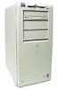
... are chassis-specific. The OptiPlex NX1 system is available only in three different chassis configurations: low-profile desktop, midsize desktop, and mini tower (see Figure 1-1). Chapters 4, 5, 6, and 7 are available in the OptiPlex NX1 chassis (see Figure 1-1). Chapters 1 through 3 and Appendix A contain information that applies to all models of computers. The Dell OptiPlex GX1 and OptiPlex NX1...
... are chassis-specific. The OptiPlex NX1 system is available only in three different chassis configurations: low-profile desktop, midsize desktop, and mini tower (see Figure 1-1). Chapters 4, 5, 6, and 7 are available in the OptiPlex NX1 chassis (see Figure 1-1). Chapters 1 through 3 and Appendix A contain information that applies to all models of computers. The Dell OptiPlex GX1 and OptiPlex NX1...

Service Manual
Page 17
... is not equipped with 65,535 colors at 75 Hz. The audio controller has analog jacks for audio jack input and output specifications. Most of the video subsystem directly to the Pentium chip set for the extra-high performance required for 3D video subsystems. This...Rage Pro (AGP 2X) video controller 4-MB synchronous graphics random-access memory (SGRAM) video memory (expandable to the ISA bus. The OptiPlex GX1 and OptiPlex NX1 systems include an integrated highperformance 64-bit accelerated graphics port (AGP) subsystem, implemented on the AMC without congesting the PCI bus ...
... is not equipped with 65,535 colors at 75 Hz. The audio controller has analog jacks for audio jack input and output specifications. Most of the video subsystem directly to the Pentium chip set for the extra-high performance required for 3D video subsystems. This...Rage Pro (AGP 2X) video controller 4-MB synchronous graphics random-access memory (SGRAM) video memory (expandable to the ISA bus. The OptiPlex GX1 and OptiPlex NX1 systems include an integrated highperformance 64-bit accelerated graphics port (AGP) subsystem, implemented on the AMC without congesting the PCI bus ...

Service Manual
Page 45
Mini tower computers OptiPlex NX1 computers PCI and ISA (PCI bus complies with MMX technology 266, 333, 350, or 400 MHz 66/100 MHz 32-KB (16-KB data ... 15 2 Mb Bus types Bus speeds PCI expansion-card connectors: Low-profile computers Midsize computers . . . . Internal cache Math coprocessor Intel Pentium II microprocessor with PCI Specification 2.1) PCI: 33 MHz; External system clock . . . . . ISA: 8.33 MHz two (one PCI connector and one ISA connector share an expansion-card slot) three (one PCI...
Mini tower computers OptiPlex NX1 computers PCI and ISA (PCI bus complies with MMX technology 266, 333, 350, or 400 MHz 66/100 MHz 32-KB (16-KB data ... 15 2 Mb Bus types Bus speeds PCI expansion-card connectors: Low-profile computers Midsize computers . . . . Internal cache Math coprocessor Intel Pentium II microprocessor with PCI Specification 2.1) PCI: 33 MHz; External system clock . . . . . ISA: 8.33 MHz two (one PCI connector and one ISA connector share an expansion-card slot) three (one PCI...

Service Manual
Page 60
..., see "Internal Visual Inspection" found in this chapter. Checks the functionality of the mouse controller and the operation of the system Run Specific Tests - Starting the diagnostics causes the Dell logo to the MS-DOS prompt: Run Quick Tests - This menu lets you choose the following options or exit to appear on...
..., see "Internal Visual Inspection" found in this chapter. Checks the functionality of the mouse controller and the operation of the system Run Specific Tests - Starting the diagnostics causes the Dell logo to the MS-DOS prompt: Run Quick Tests - This menu lets you choose the following options or exit to appear on...

Service Manual
Page 62
... in main memory, the diagnostics loads and the Diagnostics Menu appears. Before the diagnostics loads, a program tests the portion of the system Run Specific Tests - This menu lets you choose the following options or exit to appear on the monitor screen, followed by a message indicating that the... To install the external diskette drive, follow these steps: To run the diskette-based diagnostics, follow these steps: Starting the diagnostics causes the Dell logo to the MS-DOS prompt: Run Quick Tests - Tests a particular area or subsystem If the Diagnostics Menu does not appear, check the...
... in main memory, the diagnostics loads and the Diagnostics Menu appears. Before the diagnostics loads, a program tests the portion of the system Run Specific Tests - This menu lets you choose the following options or exit to appear on the monitor screen, followed by a message indicating that the... To install the external diskette drive, follow these steps: To run the diskette-based diagnostics, follow these steps: Starting the diagnostics causes the Dell logo to the MS-DOS prompt: Run Quick Tests - Tests a particular area or subsystem If the Diagnostics Menu does not appear, check the...

Service Manual
Page 68
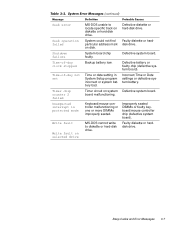
... more DIMMs faulty or improperly seated. Faulty diskette, faulty or improperly connected diskette/tape drive interface cable, or loose power cable. System could not locate specific sector or track. Diskette write-protected. Faulty keyboard controller (defective system board). Hard-disk drive failed to read error from using available memory. Read/write...
... more DIMMs faulty or improperly seated. Faulty diskette, faulty or improperly connected diskette/tape drive interface cable, or loose power cable. System could not locate specific sector or track. Diskette write-protected. Faulty keyboard controller (defective system board). Hard-disk drive failed to read error from using available memory. Read/write...
Service Manual
Page 71
... harddisk drive. Defective system board. Faulty diskette or harddisk drive. Incorrect Time or Date settings or defective system battery. MS-DOS cannot write to locate specific track on diskette or hard-disk drive. MS-DOS unable to diskette or hard-disk drive. Timer circuit on disk. Defective battery or faulty chip...
... harddisk drive. Defective system board. Faulty diskette or harddisk drive. Incorrect Time or Date settings or defective system battery. MS-DOS cannot write to locate specific track on diskette or hard-disk drive. MS-DOS unable to diskette or hard-disk drive. Timer circuit on disk. Defective battery or faulty chip...
Service Manual
Page 172
..., 1-8 internal views, 1-9, 1-11, 1-12 interrupt assignments, 1-19 jumper information, 1-18 orientation information, 1-21 service information, 1-16 specifications, technical, 1-33 troubleshooting, 2-1 upgrade options, 1-15 connectors external, 1-12 on back of low-profile computer, 1-9 on back of ...removal low-profile computer, 4-3 midsize computer, 5-5 mini tower computer, 6-4 OptiPlex NX1 computer, 7-4 DC power cables, low-profile computer, 1-25 cables, midsize and mini tower computers, 1-27 cables, OptiPlex NX1 computer, 1-32 connector pin assignments, low-profile computer, 1-23 connector...
..., 1-8 internal views, 1-9, 1-11, 1-12 interrupt assignments, 1-19 jumper information, 1-18 orientation information, 1-21 service information, 1-16 specifications, technical, 1-33 troubleshooting, 2-1 upgrade options, 1-15 connectors external, 1-12 on back of low-profile computer, 1-9 on back of ...removal low-profile computer, 4-3 midsize computer, 5-5 mini tower computer, 6-4 OptiPlex NX1 computer, 7-4 DC power cables, low-profile computer, 1-25 cables, midsize and mini tower computers, 1-27 cables, OptiPlex NX1 computer, 1-32 connector pin assignments, low-profile computer, 1-23 connector...
Service Manual
Page 176
..., low-profile computer, 4-19 removal, midsize computer, 5-22 removal, mini tower computer, 6-24 removal, OptiPlex NX1 computer, 7-16 secondary cache memory, 1-3 server-based diagnostics, 2-6 service-related information, 1-17, 1-22 SMART technology, 1-4 specifications, technical, 1-33 stand removal midsize computer, 5-4 OptiPlex NX1 computer, 7-3 subsystems audio, 1-5 expansion, 1-12 memory, 1-16 NIC, 1-6 SVGA, 1-5 switch, AC voltage selection...
..., low-profile computer, 4-19 removal, midsize computer, 5-22 removal, mini tower computer, 6-24 removal, OptiPlex NX1 computer, 7-16 secondary cache memory, 1-3 server-based diagnostics, 2-6 service-related information, 1-17, 1-22 SMART technology, 1-4 specifications, technical, 1-33 stand removal midsize computer, 5-4 OptiPlex NX1 computer, 7-3 subsystems audio, 1-5 expansion, 1-12 memory, 1-16 NIC, 1-6 SVGA, 1-5 switch, AC voltage selection...
Service Manual
Page 177
tape drives about, 1-4 removal, low-profile computer, 4-9 removal, midsize computer, 5-11 removal, mini tower computer, 6-12 technical specifications, 1-33 telephony application programming interface, 1-6 tools, recommended low-profile computer, 4-1 midsize computer, 5-1 mini tower computer, 6-1 OptiPlex NX1 computer, 7-1 troubleshooting boot routine, 2-3 diagnostics, 2-6 external visual inspection, 2-2 initial procedures, 2-1 internal visual inspection, 2-4 resource conflicts, 2-5 service-related information...
tape drives about, 1-4 removal, low-profile computer, 4-9 removal, midsize computer, 5-11 removal, mini tower computer, 6-12 technical specifications, 1-33 telephony application programming interface, 1-6 tools, recommended low-profile computer, 4-1 midsize computer, 5-1 mini tower computer, 6-1 OptiPlex NX1 computer, 7-1 troubleshooting boot routine, 2-3 diagnostics, 2-6 external visual inspection, 2-2 initial procedures, 2-1 internal visual inspection, 2-4 resource conflicts, 2-5 service-related information...


