Service Manual
Page 14
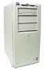
...OptiPlex NX1 chassis configurations differ primarily in the following expansion features: Number of expansion slots available for PCI/ISA expansion cards Number of available internal drive bays for EIDE/SCSI drives Number of available external drive bays for diskette, CD-ROM, or tape drives Physical size and power supply... types (the midsize and mini tower systems use the same power supply) Due to the physical differences in the four chassis configurations, a separate parts removal and replacement chapter (Chapters 4 through 7) is provided for...
...OptiPlex NX1 chassis configurations differ primarily in the following expansion features: Number of expansion slots available for PCI/ISA expansion cards Number of available internal drive bays for EIDE/SCSI drives Number of available external drive bays for diskette, CD-ROM, or tape drives Physical size and power supply... types (the midsize and mini tower systems use the same power supply) Due to the physical differences in the four chassis configurations, a separate parts removal and replacement chapter (Chapters 4 through 7) is provided for...
Service Manual
Page 55
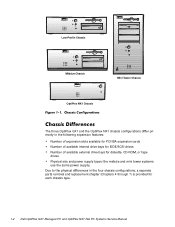
...and indications, some of these steps. No. No. If the troubleshooting procedure indicates that the system power supply is running, observe the system for your system. Troubleshoot the system power supply. Yes. No. To observe problem indications during the boot routine, follow these indicators flash on ... Routine." If one or more keys are sticking, it may be necessary to replace the keyboard. Do these steps: Does the fan run normally? Proceed to step 4. Yes. Troubleshoot the system power supply. Does the inspection reveal any indications of problems. NOTE: Most of the steps...
...and indications, some of these steps. No. No. If the troubleshooting procedure indicates that the system power supply is running, observe the system for your system. Troubleshoot the system power supply. Yes. No. To observe problem indications during the boot routine, follow these indicators flash on ... Routine." If one or more keys are sticking, it may be necessary to replace the keyboard. Do these steps: Does the fan run normally? Proceed to step 4. Yes. Troubleshoot the system power supply. Does the inspection reveal any indications of problems. NOTE: Most of the steps...

Service Manual
Page 75
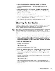
CD-ROM drive in external bay power supply system board securing buttons (2) diskette drive drive cage for external drive internal harddisk drive chassis intrusion switch expansion-card cage front of computer Removing and Replacing Parts on the Low-Profile Chassis 4-3
CD-ROM drive in external bay power supply system board securing buttons (2) diskette drive drive cage for external drive internal harddisk drive chassis intrusion switch expansion-card cage front of computer Removing and Replacing Parts on the Low-Profile Chassis 4-3

Service Manual
Page 79
... drive interface cable power supply 3.5-inch diskette drive 5.25-inch drive bay and bracket hard-disk drive DSKT connector EIDE cable secondary EIDE interface connector (IDE2) primary EIDE interface connector (IDE1) The following subsections contain removal/replacement procedures for drives installed... in the following subsections. Refer to this figure when you perform any of drive hardware that can be installed in the computer. Removing and Replacing Parts on the Low-Profile Chassis 4-7...
... drive interface cable power supply 3.5-inch diskette drive 5.25-inch drive bay and bracket hard-disk drive DSKT connector EIDE cable secondary EIDE interface connector (IDE2) primary EIDE interface connector (IDE1) The following subsections contain removal/replacement procedures for drives installed... in the following subsections. Refer to this figure when you perform any of drive hardware that can be installed in the computer. Removing and Replacing Parts on the Low-Profile Chassis 4-7...

Service Manual
Page 83
Then slide the system power supply toward the back of the chassis, and hook the tabs into the right side of the chassis. power supply power-supply mounting screw To remove the system power supply, follow these steps: When you replace the system power supply, place it down inside the chassis and against the right side of the power supply. Removing and Replacing Parts on the Low-Profile Chassis 4-11
Then slide the system power supply toward the back of the chassis, and hook the tabs into the right side of the chassis. power supply power-supply mounting screw To remove the system power supply, follow these steps: When you replace the system power supply, place it down inside the chassis and against the right side of the power supply. Removing and Replacing Parts on the Low-Profile Chassis 4-11

Service Manual
Page 97
3.5-inch diskette drive diskette/tape drive interface cable power supply system board external drive bays hard-disk drive bracket hard-disk drive interface cable expansion-card cage Removing and Replacing Parts on the Midsize Chassis 5-3
3.5-inch diskette drive diskette/tape drive interface cable power supply system board external drive bays hard-disk drive bracket hard-disk drive interface cable expansion-card cage Removing and Replacing Parts on the Midsize Chassis 5-3

Service Manual
Page 103
... Midsize Chassis 5-9 system power supply DC power cable diskette/tape drive interface cable 3.5-inch diskette drive hard-disk drive bracket EIDE cable DSKT connector primary EIDE interface connector (IDE1) secondary EIDE interface connector (IDE2) The following subsections. Figure 5-7 shows an example of the procedures in the following subsections contain removal/replacement procedures for drives...
... Midsize Chassis 5-9 system power supply DC power cable diskette/tape drive interface cable 3.5-inch diskette drive hard-disk drive bracket EIDE cable DSKT connector primary EIDE interface connector (IDE1) secondary EIDE interface connector (IDE2) The following subsections. Figure 5-7 shows an example of the procedures in the following subsections contain removal/replacement procedures for drives...

Service Manual
Page 121
power supply system board external drive bays hard-disk drive bracket riser board expansion-card cage Removing and Replacing Parts on the Mini Tower Chassis 6-3
power supply system board external drive bays hard-disk drive bracket riser board expansion-card cage Removing and Replacing Parts on the Mini Tower Chassis 6-3
Service Manual
Page 147
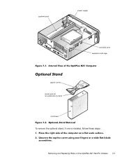
system board power supply hard-disk drive expansion-card cage captive screw locator pins (2) (on underside of stand) front bezel To remove the optional stand, if one is installed, follow these steps: Removing and Replacing Parts on the OptiPlex NX1 Net PC Chassis 7-3
system board power supply hard-disk drive expansion-card cage captive screw locator pins (2) (on underside of stand) front bezel To remove the optional stand, if one is installed, follow these steps: Removing and Replacing Parts on the OptiPlex NX1 Net PC Chassis 7-3
Service Manual
Page 176
See computer 6 power supply (continued) voltage ranges, OptiPlex NX1 computer, 1-30 precautionary measures low-profile computer, 4-1 midsize computer, 5-1 mini tower computer, 6-1 OptiPlex NX1 computer, 7-1 remote management features, 1-16 removing and replacing parts low-profile computer, 4-1 reset button removal low-profile computer, 4-4 midsize computer, 5-6 mini tower computer, 6-6 resource conflicts eliminating, 2-5 riser board removal low-profile computer, 4-14...
See computer 6 power supply (continued) voltage ranges, OptiPlex NX1 computer, 1-30 precautionary measures low-profile computer, 4-1 midsize computer, 5-1 mini tower computer, 6-1 OptiPlex NX1 computer, 7-1 remote management features, 1-16 removing and replacing parts low-profile computer, 4-1 reset button removal low-profile computer, 4-4 midsize computer, 5-6 mini tower computer, 6-6 resource conflicts eliminating, 2-5 riser board removal low-profile computer, 4-14...


